Do you have a question about the ATEQ F580 and is the answer not in the manual?
Compact air/air leak detector for controlling air-tightness of parts on production lines.
Details on pressure drop and test pressure measurement ranges and accuracy.
Direct, indirect, and sealed component measurement methods.
Explains tests with reference, without reference, and with central naught.
Details the 5 phases of the direct measurement cycle.
Explains symbols used in the manual for connectors, warnings, and functions.
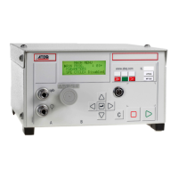
The ATEQ F580 is supplied in a 19" case and operates on 90-260 V AC.
Network must not exceed 9 heads/3 I/O modules; switch off before intervention; cable length limit.
Control unit and head electric supply requirements and connection methods.
Details on start/stop switch, connector layout, and electrical power supply.
Identifies key components and displays on the front panel of the ATEQ F580.
Explains the function of validation, escape, cycle, and navigation keys.
Describes the LOCKED and ACCESS positions of the lock switch.
Details the 16-line LCD display, 14-character LED display, and indicator lights.
Explains the use of rapid connectors for pressure and calibration verification.
Steps to connect power supply and initiate instrument start-up.
Procedure to identify and address measurement units in the network.
Setting inputs/outputs according to extended, standard, or compact modes.
Indicates when the central module communicates with network instruments.
Procedure to create a test program for a measurement unit using the central unit keyboard.
Accessing four test types: Leak Test, Blockage, D. Mode, Operator.
Procedure for setting test cycle parameters, identical for each case.
Procedure to copy and paste parameters from one program to another.
Steps to delete a test program from the instrument.
How to start a test cycle on one or more measurement units.
Procedure to start special cycles, e.g., regulator adjustment.
Procedures for adjusting test pressure with mechanical regulators.
Overview of the central unit's menu structure.
Manages measurement unit test cycles, active programs, and special cycles.
Manages test parameters for measurement units, including copy-paste function.
Manages central unit display modes (LCD, LED, Standard, Compact, Results, Curve).
Configures the central unit, network, and accessories.
Accesses servicing of measurement units, parameters, and the network.
Displays results measured by different measurement units.
Menu structure for the F5 head measurement unit.
Lists available special cycles for operator adjustment and servicing.
Enables checks on instrument parts like sensors and valves.
Lists accessories provided with the instrument.
Lists optional accessories for the instrument.
Used to check instrument calibration with various leak rates.
Details needle valves for calibrating leakage and the CDF leak/flow calibrator.
Module for remote management of heads, simplifying cabling.
Module for network connection, cancelling over-intensity.
Wiring diagram for a network with central, heads, PS5 modules, and power supplies.
Board for replacing series 3 with series 5 instruments without cabling modification.
Connectors for reliable assemblies, self-locking via pneumatic valve.
Describes network communication errors for the central unit.
Lists problems and displayed messages for errors occurring on a single head.
Addresses seal contamination and cleaning as a remedy.
Troubleshooting steps for airtight cell issues.
Details cabinet dimensions, electric supply, connections, weight, format, and temperatures.
Mechanical drawings of the F580 control unit.
Table for converting pressure units (Pa, kPa, bar, mbar, etc.).
| Brand | ATEQ |
|---|---|
| Model | F580 |
| Category | Security Sensors |
| Language | English |