Chapter 5 - Accessories
UM-18400E-U ATEQ F580 User manual Page 152/168
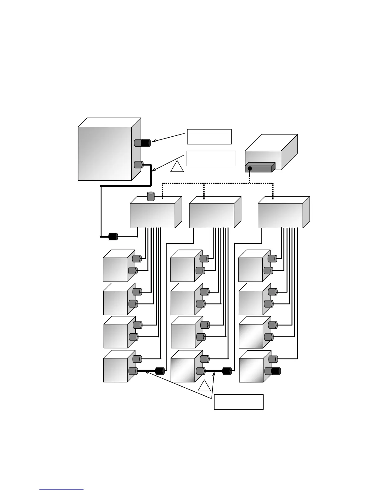
2.7. INSTALLATION SYNOPSIS
The following diagram represents the wiring of a network including a central, several
measurement units (heads), PS5 modules and external 24 V DC power supplies.
The external input/output modules can be place in any measurement unit location.
The standard 4A or 14A power supplies are adapted to the most common applications.
Otherwise, it is necessary to install a power supply capable of supporting a power in
excess of the one installed.
PS5 junction
box module
Number 1
CENTRAL
F20A n°1
F20A n°4
24 V DC
power supply
F20A n°2
F20A n°3
PS5 junction
box module
Number 1
PS5 junction
box module
Number 1
F20A n°5
F20A n°8
F20A n°6
F20A n°7
I/O n°2
I/O n°3
Female network
cap
Network cable with
24VDC seperation
Network cables with
24VDC seperation
F20A n°9
I/O n°1
!
!