Table 2-2
2.2 Unpacking
2.2.1 Packing List
EnerLog and accessories can be found as below figure 2-2:
Item
Name
Amount
1
EnerLog
1 pc
2 12V power adapter
1 pc
3
RS485 and power supply
i n t e r f a c e 2 lo c k w i r e
terminal
5 pcs
4
EnerLog user manual 1 pc
5 Network cable (1 meter) 1 pc
6 ATESS certificate 1 pc
Table 2-4
4 5
Item Name Function
A
B
C
D
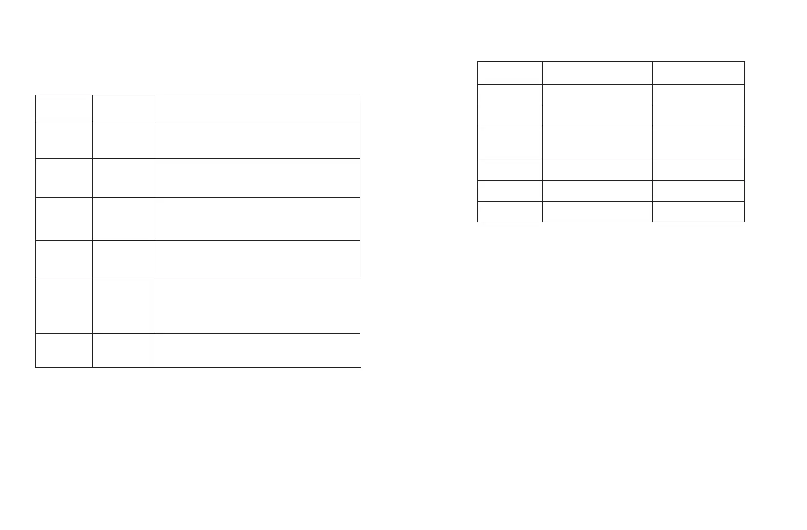
2.1.2 Indicator status description
EnerLog has a total of 6 LED lights, through which the running status of EnerLog can
be displayed.
STATUS LED
System status light
Fast flashing: program upgrade
Interval flashing: normal operation
LED off: abnormal operation
RS485-3 LED
Monitoring device data indicator, the number of
periodic flashing represents the number of devices
communicating normally with the RS485-3 channel
and EnerLog.
RS485-2 LED
Monitoring device data indicator, the number of
periodic flashing represents the number of devices
communicating normally with the RS485-2 channel
and EnerLog.
RS485-1 LED
Monitoring device data indicator, the number of
periodic flashing represents the number of devices
communicating normally with the RS485-1 channel
and EnerLog.
NETWORK LED
Network indicator
The off state means that it is not connected to the
network normally;
The steady state indicates that the network is
connected normally.
POWER LED
Power Indicator
Steady on: power supply is normal
Off: Abnormal power supply
E
F