3.3.1 RS485 cable connection
3.3 Connect with device
EnerLog can communicate with energy storage inverters, BMS and other equipment to
achieve the purpose of data collection.
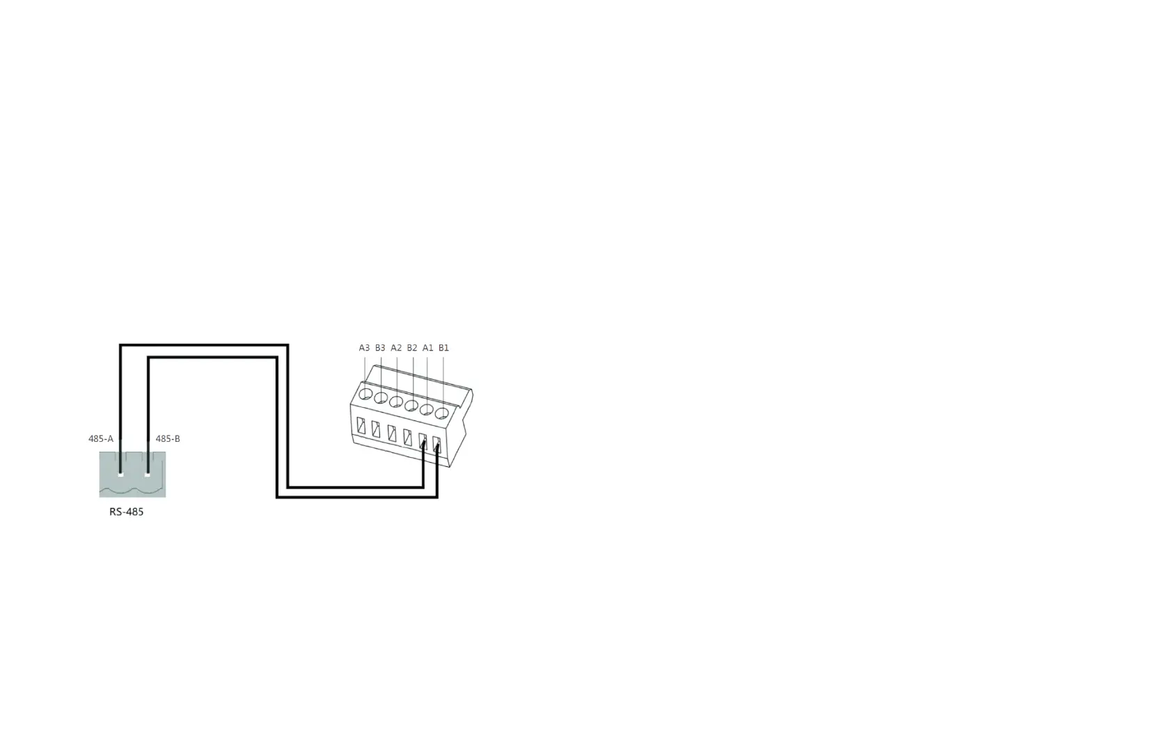
1.EnerLog (master) and device (slave) communicate through RS485 wired
connection. The 485-A on the RS485 port of the device corresponds to A1, A2 or A3 on
the EnerLog 485 port, and the 485-B on the RS485 port corresponds to Corresponding
to B1, B2 or B3 on the EnerLog 485 port. The following is a schematic diagram of the
connection between EnerLog and the inverter:
8
9
2.The inverter and the inverter are connected to the EnerLog through the RS485 line
parallel connection, and the RS485 wired communication connection is adopted. The
EnerLog can stably monitor up to 30 devices (each RS485 channel connects 10
devices).
The functions of the A1B1, A2B2, and A3B3 channels are the same.
3.Other 485 communication equipment such as: BMS, combiner box, etc., the
connection method is the same as that of the inverter.
4. Notice:
(1) RS485 shielded wire must be grounded (PE) during communication to avoid
affecting the stability of communication.
(2) The three 485 channels provided by EnerLog are all connected with 120 ohm
matching resistance, so when one or more inverters communicate with EnerLog for
485, one inverter must be connected with 120 ohm matching resistance to avoid
affecting communication (In a 485 channel, only one of multiple inverters can be
connected to matching resistance, and multiple inverters cannot be connected to
matching resistance at the same time), it is recommended that the most remote
inverter is connected to matching resistance.
(3) Environmental detectors, combiner boxes and other equipment must be
manufacturers designated by ATESS, otherwise monitoring cannot be achieved.