Manual, F/T Sensor, Data Acquisition (DAQ) Systems
Document #9620-05-DAQ.indd-20
Pinnacle Park • 1031 Goodworth Drive • Apex, NC 27539 • Tel: 919.772.0115 • Fax: 919.772.8259 • www.ati-ia.com • Email: info@ati-ia.com
70
Appendix A – Tool Transformation
The tool transformation allows you to enter a series of tool transformations in order to measure the forces and
torques acting at a point other than the origin of the sensor. If you specify both rotations and displacements within
a particular tool transformation, displacements are performed rst, in the order DX, DY, DZ, then rotations are
performed, in the order RX, RY, RZ. If it is critical that rotations occur before displacements, entering a tool
transformation with only rotations before entering a second tool transformation with displacements.
Tool Transformations Screen Controls:
• Displacement DX, DY, and DZ: The displacement along each axis is measured in the distance
component of the calibration’s torque units, so if the sensor was calibrated to use Newton-meters as
the torque unit, the displacement is measured in meters.
• Rotations RX, RY, and RZ: The rotation about each axis, in radians.
• Add: Adds the current tool transformation to the transformation queue.
• Remove: Removes the highlighted transformation from the queue, also lls the displacement and
rotation controls with the values of the removed transformation.
• Cancel: Returns to the main form without applying any changes made to the transformation queue.
• Apply Transformation: Applies transformations in the queue and returns to the main form.
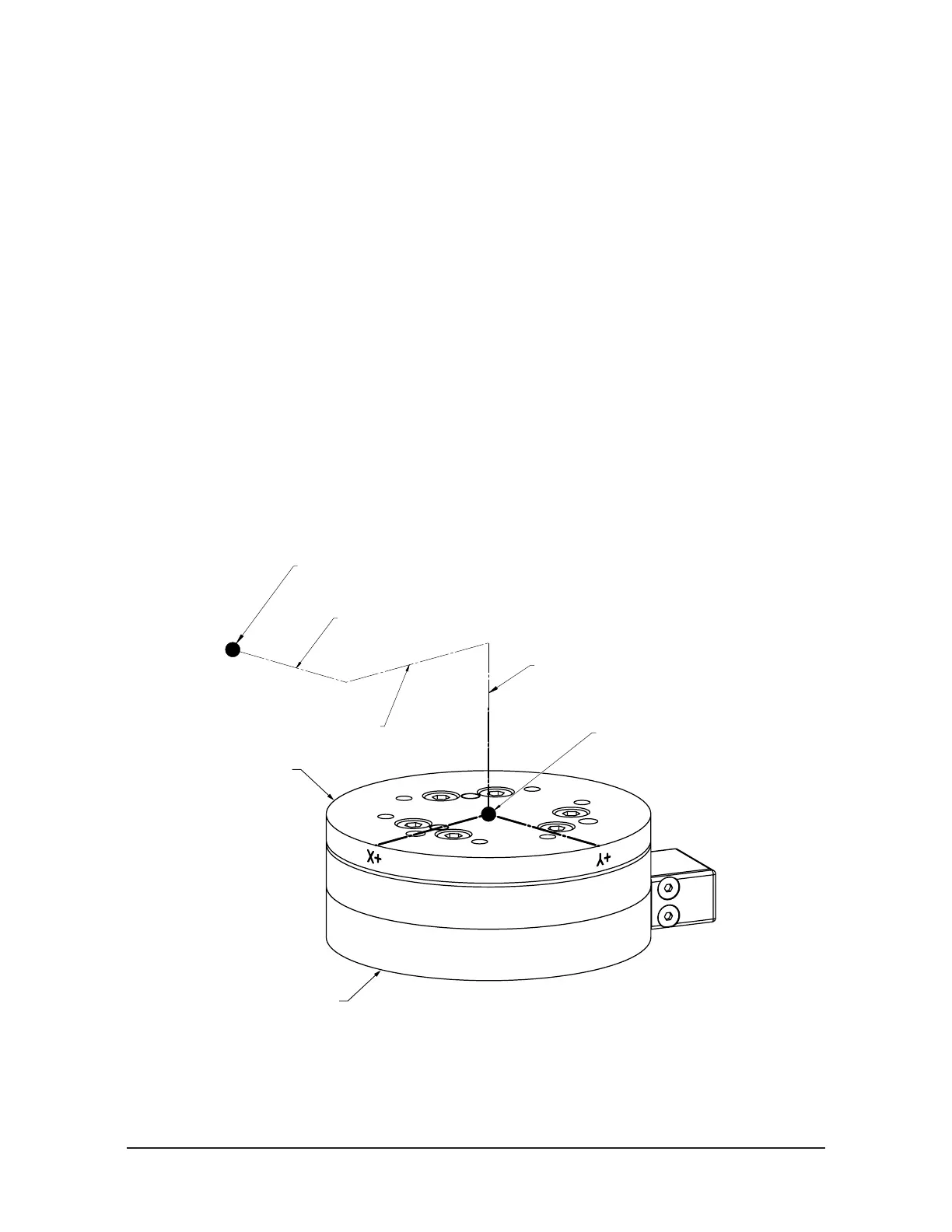
Displacement allows the customer to move the sensing reference frame origin along the X, Y,
and Z axes. Displacement should be calculated and values should be entered before rotation.
Displacement is measured in units which are set as either Nm or in-lbs. on the Calibration Screen.
Figure A.1—Displacement of Sensing Reference Frame Origin
Z+
Sensing Reference Frame Origin
(Factory Set)
Sensing Reference Frame Origin
(Customer Applied)
Origin movement along X Axis
Origin movement along Y Axis
Origin movement along Z Axis
X+ Y+
X-Y-
Z-
Tool Side of Transducer
Robot Side of Transducer