■ Electrical connections
• Before any maintenance operation, ensure
that the general power supply is switched off .
• Specifi cations of electricity supply
The electrical installation must be carried out in
accordance with current regulations.
Electrical connections will only be made once all
other installation operations (fastening, assembly,
etc.) have been completed.
Warning!
The contract signed with the energy provider must
be suffi cient not only to cover the heat pump's power
requirements but also the combined sum of all the
appliances likely to be operating at the same time. If
the power is too low, check the power rating stated
in your contract with your energy provider.
Never use a power socket for the power supply.
The heat pump must be supplied directly with power
(without external switch) by special protected leads
from the electric panel via dedicated bipolar circuit
breakers, C curve for the outdoor unit, C curve for
the electrical heating and domestic water backups
(see tables
page 35).
The electrical installation must be fi tted with a 30mA
RCD.
This appliance is designed to operate using a
nominal voltage of 230 V +/- 10%, 50 Hz.
• General remarks on electrical connections
It is essential to maintain neutral-phase polarity
when making electrical connections.
Rigid wires are preferable for fi xed installations,
particularly in a building.
Tighten the cables using the cable glands to prevent
the feed wires from being accidentally disconnected.
The earth connection and its continuity must be
ensured.
• Cable glands
To ensure the stability of power (Low Voltage) and
sensor (Extra-Low Voltage) cables, it is essential
that the cable glands are tightened according to the
following recommendations:
Size of cable
gland (PE)
(mm)
Diameter of
cable
(mm)
Cable gland
tightening
torque
(check-nut)
(N.m)
Coupling net
tightening
torque
(N.m)
PG7 1 to 5 1.3 1
PG9 1.5 to 6 3.3 2.6
PG16 5 to 12 4.3 2.6
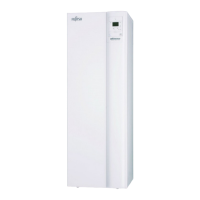
• Connecting to screw terminals
The use of ring, spade or blade terminals or
caps is prohibited.
- Always select wire that complies with current
standards.
- Bare the end of the wire to around 25 mm.
- With round end pliers, form a loop with a diameter
which matches the tightening screws on the
terminal.
- Tighten the terminal screw fi rmly onto the
loop created. Insuffi cient tightening can cause
overheating, leading to breakdown or even fi re.
Rigid wire
Loop
25 mm
Spade
or blade
terminal
on fl exible
wire
is prohibited
Screw and special
washer
Terminal
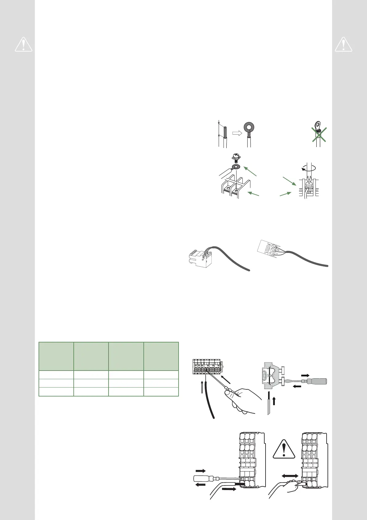
• Connecting to controller boards
- Remove the corresponding connector and make
the connection.
Pre-cabled bundle connector and/or screw connector
• Connecting to spring terminals
- Bare the end of the wire to around 12 mm.
- Push the spring with a screwdriver so that the wire
enters the cage.
- Slide the wire into the opening provided for this
purpose.
- Remove the screwdriver and then check that the
wire stays gripped by the cage by pulling on it.
2
1
3
1
3
2
4

 Loading...