EasyManua.ls Logo

Atlas Copco Elektronikon Mk5 - User Manual

Atlas Copco Elektronikon Mk5
24 pages
Print Icon
To Next Page IconTo Next Page
Loading...
13/08/2013 PM 9845 0187 01 Page 1 of 24
User guide
1. General Information
Elektronikon Mk5 Gateway Module
Document Number : 9845 0187 01
Document Edition : 15
Concerning : Units with Elektronikon Mk5 gateway module
Preliminary Operations :
Safety Instructions : General
Persons Required : 1
Special Tools :
Consumables :
2. Document Overview
This document covers the following subjects:
1.
General Information ..................................................................................................................................................... 1
2.
Document Overview ..................................................................................................................................................... 1
3.
Safety first .................................................................................................................................................................... 3
4.
Copyright Notice ........................................................................................................................................................... 4
5.
Document Information and History ............................................................................................................................... 4
6.
Safety Precautions ....................................................................................................................................................... 5
6.1.
Safety icons ............................................................................................................................................................. 5
6.2.
Safety precautions during installation ...................................................................................................................... 5
6.3.
Safety precautions during operation ........................................................................................................................ 6
6.4.
Safety precautions during maintenance or repair .................................................................................................... 7
7.
Preface ......................................................................................................................................................................... 8
8.
Physical Set-up ............................................................................................................................................................ 8
8.1.
Modbus and/or Profibus in the network ................................................................................................................... 8
8.2.
Gateway module ...................................................................................................................................................... 9
8.3.
Gateway module ...................................................................................................................................................... 9
9.
Software installation and configuration ....................................................................................................................... 10
9.1.
Display menu folder structure ................................................................................................................................ 10
9.1.1.
Mainscreen folder [ ] ....................................................................................................................................... 10
9.1.2.
General Settings folder [ GE ] ............................................................................................................................ 10
9.1.3.
Compressors folder [ CP ] ................................................................................................................................. 15
10.
Gateway Display Description ..................................................................................................................................... 16
10.1.
Icons ...................................................................................................................................................................... 16
10.2.
Leds ....................................................................................................................................................................... 16
10.3.
Keyboard ............................................................................................................................................................... 16
10.4.
Passwords / Access Codes ................................................................................................................................... 17

Other manuals for Atlas Copco Elektronikon Mk5

Question and Answer IconNeed help?

Do you have a question about the Atlas Copco Elektronikon Mk5 and is the answer not in the manual?

Summary

1. General Information

2. Document Overview

3. Safety first

4. Copyright Notice

5. Document Information and History

6. Safety Precautions

6.1. Safety icons

Explains standard safety symbols used in the manual for warnings and notes.

6.2. Safety precautions during installation

Outlines critical safety measures and precautions to be followed during equipment installation.

6.3. Safety precautions during operation

Details essential safety guidelines for operating the equipment safely and correctly.

6.4. Safety precautions during maintenance or repair

Provides safety instructions and procedures for performing maintenance and repair tasks.

7. Preface

8. Physical Set-up

8.1. Modbus and;or Profibus in the network

Describes the physical setup for connecting Modbus and Profibus to the controller network.

8.2. Gateway module

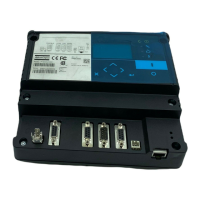
Details the Gateway module, its purpose, and the connections required for its operation.

8.3. Gateway module

Specifies the pin-layout of the 9-pin Sub-D connector for the Gateway module.

9. Software installation and configuration

9.1. Display menu folder structure

Illustrates the hierarchical structure of the module's display menu and navigation.

9.1.1. Mainscreen folder [ ]

Describes the Mainscreen folder, its function, and behavior within the module's interface.

9.1.2. General Settings folder [GE]

Explains the General Settings folder and its subfolders for configuring module parameters.

10. Gateway Display Description

10.1. Icons

Explains the meaning and interpretation of various icons displayed on the Gateway module.

10.2. Leds

Describes the function and status indicated by the LEDs on the Gateway module.

10.3. Keyboard

Details the functions of the keyboard keys for navigating and interacting with the module.

10.4. Passwords; Access Codes

Provides information on entering customer passwords and access codes for system security.

11. Modbus Protocol Implementation

11.1. Supported Modbus specification

Lists the supported specifications and parameters for the Modbus protocol variant.

11.2. Supported Modbus functions

Details the Modbus message types and functions supported by the Elektronikon Mk5 controllers.

11.3. Function code - data field

Explains the Modbus function code and data field conventions in responses and exceptions.

11.4. Exception codes

Lists and explains various exception codes returned by the Modbus protocol.

11.5. Examples

Provides practical examples of Modbus communication sequences.

11.5.1. Illegal Data Address

Illustrates a Modbus request and answer for an illegal data address scenario.

11.5.2. Outlet Pressure and Outlet Pressure Status

Shows example Modbus requests and answers for outlet pressure and status.

11.5.3. Change the active pressure band

Demonstrates Modbus communication to change the active pressure band setting.

11.5.4. Start the machine

Provides an example of Modbus commands to start the machine.

12. Profibus Protocol Implementation

12.1. Protocol Specification

Outlines the basic specifications for the Profibus-DP V0 protocol implementation.

12.2. Master-slave concept

Explains the master-slave principle governing Profibus communication.

12.3. Buffer structure

Describes the structure and length of buffers used in Profibus data transfer.

12.4. Exception codes

Lists and explains exception codes specific to the Profibus protocol.

12.5. Examples

Provides practical examples of Profibus communication sequences.

Overview

The Elektronikon Mk5 Gateway Module is a serial communication module designed to facilitate Modbus and/or Profibus connections to an Elektronikon MkIV and/or Elektronikon Mk5 compressor controller network. It acts as a Modbus/Profibus proxy, allowing access to all compressors within the network, with each compressor having its own Modbus address. Additionally, the module functions as a bridge to access data stored in the CAN node's Object Dictionary. For correct operation, this bridge module must be assigned a slave node ID. From the master's perspective, the module serves as an access point for information within the CANBUS network.

Function Description:

The primary function of the Gateway Module is to enable communication between a master device (e.g., a PC or PLC) and a network of Atlas Copco compressors equipped with Elektronikon MkIV or Mk5 controllers via Modbus or Profibus protocols. This is achieved by integrating the module into the existing CAN-based compressor network. The module translates communication between the Modbus/Profibus master and the CAN network, acting as an intermediary.

The module supports both Modbus and Profibus protocols. For Modbus, it operates in RTU mode with a binary coding system and RS485 physical layer. It supports various baud rates ranging from 9600 bps to 460800 bps, with options for even, odd, or no parity control, and 1 or 2 stop bits. Error checking is performed using CRC16. The supported Modbus functions include reading coil registers (Function 01), reading holding registers (Function 03), and presetting single registers (Function 06). It's important to note that for Elektronikon Mk5 controllers, direct parameter changes are not always possible; users should consult the address mapping document for adjustable parameters.

For Profibus, the module adheres to the standard Profibus-DP V0 protocol, utilizing RS485. It supports baud rates from 9.6k to 12M. Features like Autobaud are supported, while Freeze Mode, Sync Mode, Slave Node Address Change, and Diagnostics are not. The module does not have PTO or PNO certification, which is not mandatory for Profibus DP. The Profibus communication follows a master-slave concept, where the master initiates all communication and the slave generates replies. The buffer structure for Profibus can handle lengths of 8, 16, 32, and 64 bytes, split into a 1-byte header and 'n' data records (7 bytes each). Not all functions allow more than one data record transfer; read operations can handle multiple records, while write operations are limited to a single data record per cycle.

The module's software and configuration are managed through AC Service personnel using AC Speci5 for initial download and qualified Atlas Copco personnel using AC Modi5 for subsequent configuration. The display menu structure allows users to navigate through various settings, including General Settings, Communication parameters (Modbus Engine, Profibus Engine, EtherNet settings, CAN Engine), Password settings, Program Information, and Compressor parameters.

Important Technical Specifications:

  • Communication Protocols: Modbus RTU (RS485), Profibus-DP V0 (RS485), CAN.
  • Modbus Baud Rates: 9600, 19200, 38400, 57600, 115200, 230400, 460800 bps.
  • Modbus Parity: None, Even, Odd.
  • Modbus Stop Bits: 1, 2.
  • Modbus Error Checking: CRC16.
  • Supported Modbus Functions: Read Coil Register (01), Read Holding Register (03), Preset Single Register (06).
  • Profibus Baud Rates: 9.6k, 19.2k, 45.45k, 93.75k, 187.5k, 500k, 1.5M, 3M, 6M, 12M.
  • Profibus Buffer Lengths: 8, 16, 32, 64 bytes (1 byte header + n*7 byte data records).
  • Connections:
    • 6x36: 24Vac power supply.
    • 6x20: Compressor network (CAN).
    • 6x25: PC connection for application download.
    • 6x22: RS485 Modbus line.
    • 6x37: Profibus line.
  • RS485A Pin-layout (9 pin Female Sub-D Connector):
    • Pin 1: GND
    • Pin 2: Reserved
    • Pin 3: B-signal
    • Pin 4: Reserved
    • Pin 5: GND (galvanic isolated)
    • Pin 6: +5V (galvanic isolated)
    • Pin 7: Reserved
    • Pin 8: A-signal
    • Pin 9: Reserved
  • CAN Channels: Primary, Secondary.
  • CAN Status Priority Settings: Off, Normal, High, Request.
  • Power: 24Vac.

Usage Features:

The module provides a user-friendly interface through its display and keyboard for configuration and monitoring.

  • Display Menu Navigation: Users can browse through folders like "Mainscreen," "General Settings," and "Compressors" using Left and Right buttons.
  • Setting Alteration: When a setting is reached, its value is displayed. Pressing Enter allows the user to modify the value (which will blink), using Up or Down buttons. Changes can be undone with Cancel or stored with Enter.
  • Modbus Engine Control: The Modbus Engine can be started or stopped, though baud rate, parity, and stop bit settings are inaccessible when active.
  • Profibus Engine Control: Similarly, the Profibus Engine can be started or stopped, with SlaveAddress and DataRecords settings becoming inaccessible when active.
  • EtherNet Configuration: IP Address, Network Mask, and Gateway settings can be adjusted.
  • CAN Engine Control: The CAN Engine can be started or stopped, and the CAN Channel (Primary/Secondary) can be selected, though the channel setting is inaccessible when the engine is active.
  • Compressor Monitoring: The "Compressors" folder provides access to 31 subfolders (CP01 to CP31), each detailing compressor parameters, CAN Status, Modbus Address, and Information (cycle times for CAN Normal, CAN High, and Modbus answering speed).
  • Password Protection: The "Password Settings" folder allows enabling/disabling and altering customer passwords, with different blinking key patterns indicating the type of password required (Customer Password, Access Code, New Customer Password).
  • Program Information: The "Program Information" folder displays details such as Program Number, Program Revision, Operating System, and Boot Software.
  • Visual Indicators (Icons):
    • Blinking compressor icon: Machine in CAN Error.
    • On/Off CAN engine icon: Indicates CAN engine running/stopped.
    • On/Off Modbus engine icon: Indicates Modbus engine running/stopped.
    • On/Off Profibus engine icon: Indicates Profibus engine running/stopped.
    • On/Blinking machine icon: Indicates machine defined/enabled to request data (On) or settings (Blinking).
  • LED Indicator: A lightning bolt LED indicates the Gateway module is powered on. No other LEDs are used during application operation.

Maintenance Features:

The manual emphasizes safety precautions for installation, operation, and maintenance, highlighting the importance of authorized personnel and adherence to local regulations.

  • General Precautions: All work must be performed by authorized, trained, specialized personnel, observing safe working practices and local safety requirements. Before any non-routine checks or maintenance, the device must be stopped, and the power isolating switch opened and locked.
  • Installation Precautions:
    • Place the device in a cool and clean ambient air environment.
    • Ensure connected machines are stopped, de-energized, and isolating switches locked during interventions.
    • Electrical connections must comply with local codes, be earthed, and protected by fuses.
    • Affix warning signs ("This machine may start without warning") for machines controlled by central systems.
    • Install manual valves to isolate compressors in multiple systems; do not rely on non-return valves.
    • Never remove or tamper with safety devices.
  • Maintenance/Repair Precautions:
    • Use only correct tools and genuine spare parts.
    • Attach warning signs ("work in progress; do not start") to starting equipment.
    • Take precautions for remotely controlled machines to ensure no one is working on them.
    • Never use flammable solvents or carbon tetrachloride for cleaning parts; take safety precautions against toxic vapors.
    • Maintain cleanliness during maintenance; cover parts and openings.
    • Never use open flame for interior inspection.
    • Ensure all regulating and safety devices function properly and are not put out of action.
    • Before clearing for use, verify operating pressures, temperatures, time settings, and proper function of all control and shut-down devices.
    • Never use caustic solvents that can damage air net materials.
  • Disposal: Units and used parts should be disposed of in an environmentally friendly and safe manner, in line with local recommendations and legislation.

The module's design and documentation aim to ensure safe and efficient integration into compressor control systems, providing robust communication capabilities and clear operational guidelines.

Atlas Copco Elektronikon Mk5 Specifications

General IconGeneral
BrandAtlas Copco
ModelElektronikon Mk5
CategoryGateway
LanguageEnglish