6 Operating instructions
Initial start-up
The operator must apply all relevant Safety precautions. Also consult section Problem solving.
For the location of the air outlet valve and the drain connections, see sections Introduction and
Condensate system.
Step Action
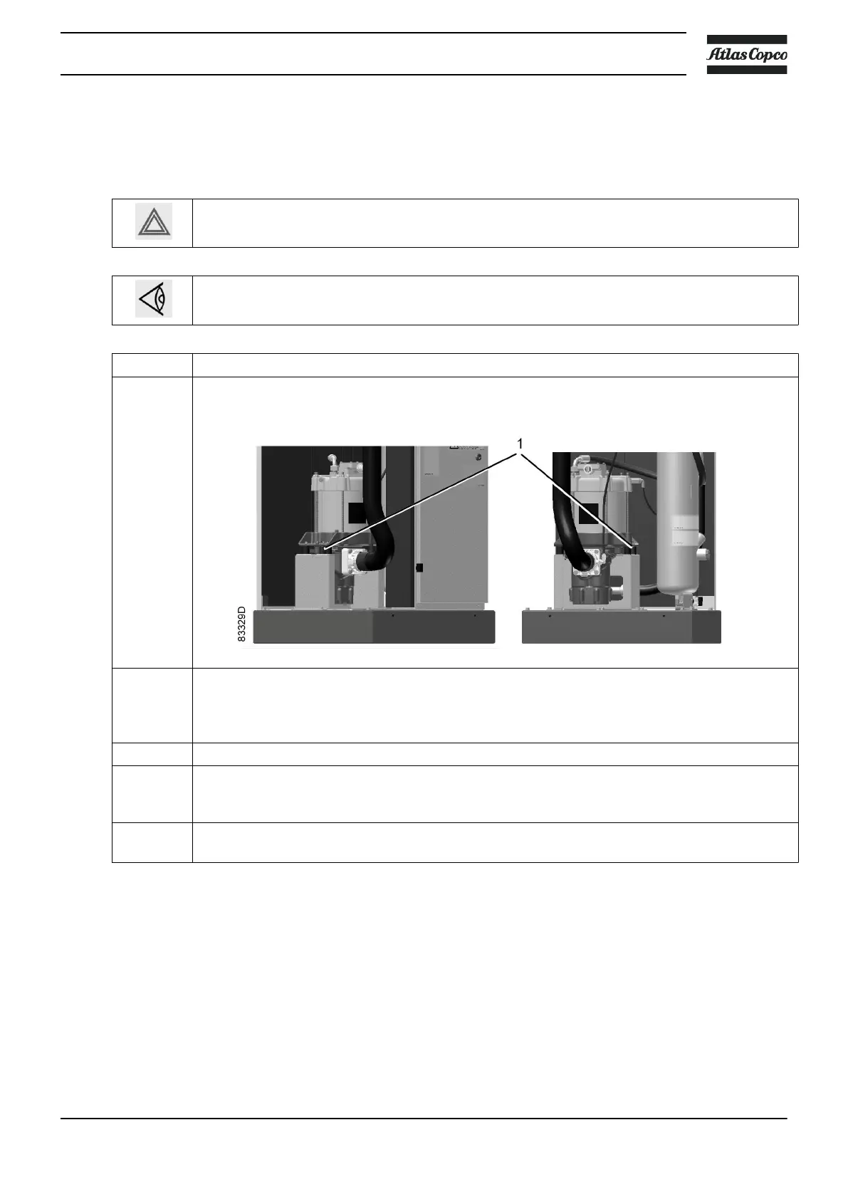
1 Remove the canopy panel(s) in order to get access to the internal components.
Remove the red transport spacers (1) and the related bolts under the motor.
2 Check that the electrical connections correspond to the local codes and that all wires are
clamped tight to their terminals.
The installation must be earthed and protected against short circuits by fuses of the inert type
in all phases. An isolating switch must be installed near the compressor.
3 Check the voltage selecting wires at the primary side of transformer T1.
4 Fit air outlet valve (AV); see section Introduction for the position of the valve.
Close the valve.
Connect the air net to the valve.
5 Fit the manual condensate drain valve (Dm).
Close the valve.
Instruction book
2920 7109 23 97
 Loading...