7
PAGE
Repair Instructions No.181.03/98
PHE 6 H / PHE 6 S
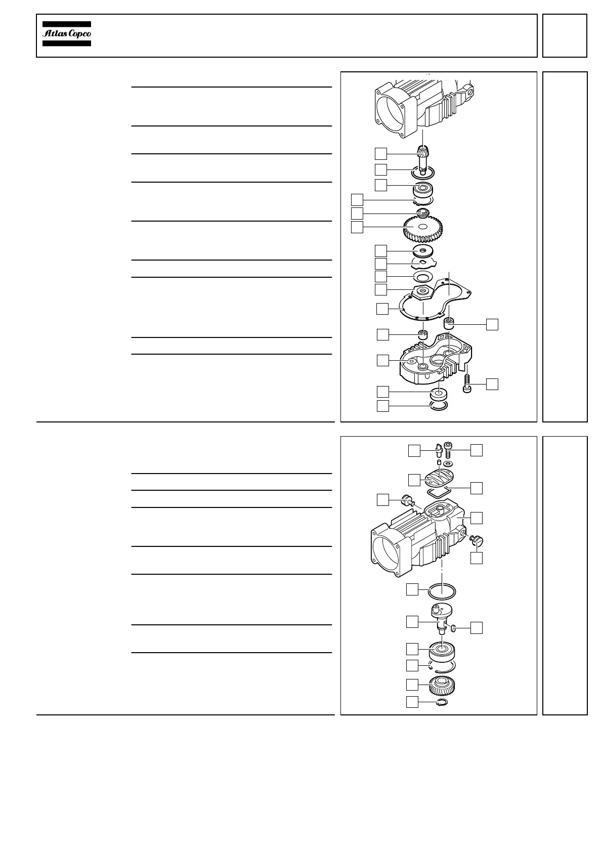
Detaching the
pinion shaft
1 Lever off the O-ring (1) and the seal (2).
2 Loosen the six screws (H) of the gear
box cover (3) and remove the gear box
cover (3) with the gasket (5).
3 Pull out the needle bearings (4) and (G)
with aid of an interior extractor.
4 Bend down the lugs of the securing
plate (8).
5 Block the drive (A) using a screwdriver
and unscrew the clutch (6) (right-handed
thread).
6 Remove the cup spring (7), the securing
plate (8), the drive (A), the friction disk (9)
and the clutch (B).
7 Remove the spring ring (C).
8 Pull out the pinion (F) with the bearing (D).
☞
Fix the end of the pinion shaft in a vice
between protective chops and hit the
housing lightly with a plastic hammer.
9 Press the bearing (D) from the pinion (F).
10Remove the O-ring (E) from the motor
housing (pillow block).
Detaching the
crankshaft
1 Loosen the two screws (A) and remove
the service cover (8) with the gasket (B)
and the valve (9).
2 Remove damaged welch plug (7).
3 Remove the spring ring (1).
4 Pull off the crank wheel (2) with aid of a
pulling-off device (service tool). Steady
the crank wheel for support.
5 Remove the key (D) from the crank-
shaft (5).
6 Remove the spring ring (3) and pull out the
crankshaft; if necessary, press out the
crankshaft through the opening in the cov-
er with aid of a suitable mandrel.
7 Press the ball bearing (4) off the crank-
shaft.
8 Remove the O-ring (6) from the gear
housing (C).
F
A
B
C
D
E
9
8
7
6
5
G
4
3
2
1
H
9
5
6
7
A
8
4
3
D
B
7
2
1
C
 Loading...