lx = 95 mm ERP-CSP (BS6195-4C)
2
bx = 1.5 mm NSGAFOeU
2
k = 70 mm
2
j = 50 mm
2
i = 35 mm
54 = green/yel.
1 = brown
2
2
2
2
2
2
2
2
2
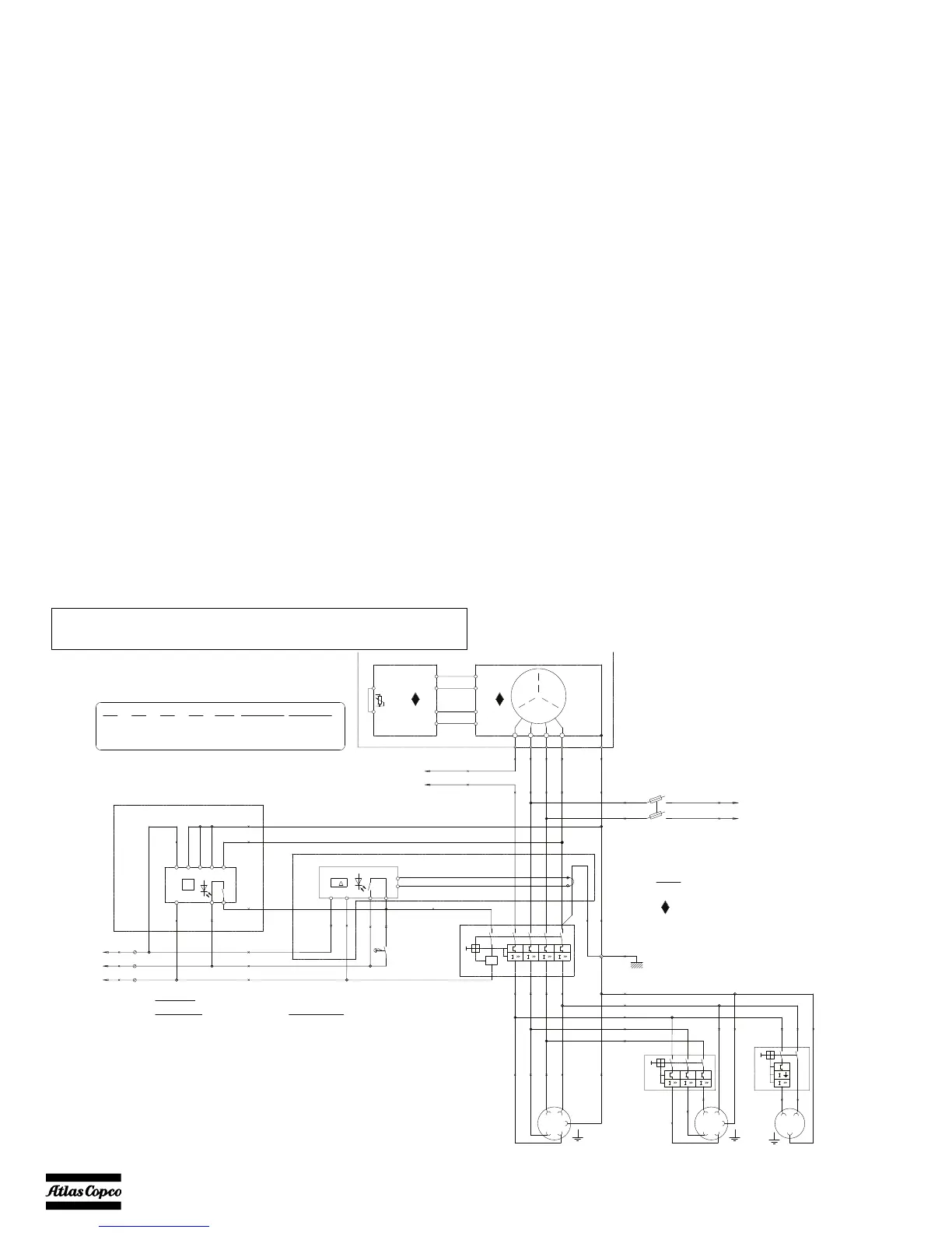
Wire size : Colour code :
Legend
a = 1 mm
b = 1.5mm
c = 2.5mm
d = 4 mm
e = 6 mm
f = 10 mm
g = 16 mm
h = 25 mm
0 = black
2 = red
3 = orange
4 = yellow
5 = green
6 = blue
7 = purple
8 = grey
9 = white
1
2
T13
A1 A2 31 34
(O)
(O)
F1
F2
13
X9
12
X9
5
X9
(*)= X2 optional on QAX30(*)= X2 optional on QAX30
(*)(*)
22
2.5mm |6mm
2
2.5mm
2
2.5mm
16A
16A|32A
16A
Q2/X2
32A
63A
32A
X1
2
6mm32A0-30A20
2
10mm
2
2.5mm
50A
20A
0-60A
0-30A
30
12
Wire Size yWire Size xQ1P1QAX
Notes
Note 1: The PE-N connection has to be made at the
alternator-side of main Circuit Breaker Q1.
See Note 1
Cubicle
Alternator
Alternator
Cubicle
Cubicle
Alternator
0V
110
E-
E+
N12
Voltage
Adjustm.
PE
f54
c1
c2
U>
Q1
N13
I n
T1
T2
S2b
a3
118
a2
13
a6
12
a3
5
T10
T7
T4
T1
T11
T8
T5
T2
T12
T9
T6
T3
400V-50Hz
T8
T11
6-
5+
PE
N1
N
V1
T2
W1
T3
U1
T1
G3
x0
U1
to Circ.Diagr ENGINE
V-meter & Control Module
N
L
16A
X3
c6
3N
c0
3L3
x6
N
x0
L3
x0
L2
x0
L1
x54
X1
L1L2
NL3
c0
2L3
c0
2L2
c0
2L1
X2
L1L2
NL3
c54
c6
N
c0
L1
16A
30mA
Q3
y54
y6
N
x54
x6
N
x0
L1
x54 x54
y0
L2
y0
L3
a6
12
a2
13
a3
5
b54
bx6
N1
a3
118
a6
12
a2
13
a3
5
a3
118
x6
N
x0
L3
x0
L2
x0
L1
Q2
a6
12
a2
13
a3
5
a0
126
a0
125
a0
W1
a0
V1
x0
1U1
x54
x6
N1
x0
W1
x0
V1
x0
1U1
x54
x6
N1
x0
W1
x0
V1
x0
U1
to Circ.Diagr ENGINE
Note: Do not connect (N) to (PE)
N14
R<
LPE
T
R
A2
A1
to Circ.Diagr ENGINE
Ampere-meter
 Loading...