7. Black anodizing provides a very durable finish, much better than paint. However, the ano-dized surface is an
electrical insulation. In order to ensure electrical bonding between the transceiver and the car chassis, shakeproof
washers must be used under all screw heads. They will cut through the anodizing. Scraping the anodizing off
around the junction points on the rear bracket(s) is also recommended. Poor grounding may lead to transmitter
instability, which will cause a regenerative or self oscillating condition. If there is any question of adequate
grounding, connect a copper braid or strap from the antenna bracket on the mobile mount to the nearest chassis
ground, either the bulkhead or transmission hump.
8. The power cable should be run from the mobile mount through the bulkhead into the engine compartment. It
should then be connected to the positive and negative terminals as close to the battery as possible. The best way
to connect directly to the battery terminal posts is by drilling and tapping for a 10-32 or 10-24 machine screw.
The red lead goes to the positive terminal, and the brown to the negative. (Or the white is positive and the black
is negative.)
9. The 25 ampere circuit breaker supplied with the kit should be installed in series with the positive lead. It is best
to mount it close to the battery end of the cable, at some convenient place on the side of a metal panel or
bracket. Sheet metal screws are supplied for this purpose. It is not important that the metal case of the circuit
breaker be grounded, since there are no connections made to the case. Cut the positive red power lead, install
No. 10 terminal lugs, and secure firmly to the circuit breaker with washers and nuts. Solder the terminal lugs.
NOTICE
The advantage of connecting directly to the battery posts is that loose battery clamps will then not affect the
transceiver connections, and the danger of intermittent voltage spikes is reduced. If drilling and tapping the battery
posts is not practical, then connect the leads to the engine end of the heavy battery cables. The negative cable will
usually be found going to a grounding bolt on the engine block, and the positive cable usually goes to a bolt on the
starter solenoid. Use proper terminal lugs at these points for connecting the leads. Battery clamps and terminals
should be cleaned and tightened periodically. Anti-corrosion grease is a good recommendation. All other electrical
connections under the hood: alternator, regulator, ignition coil,etc.,should also be checked and tightened.
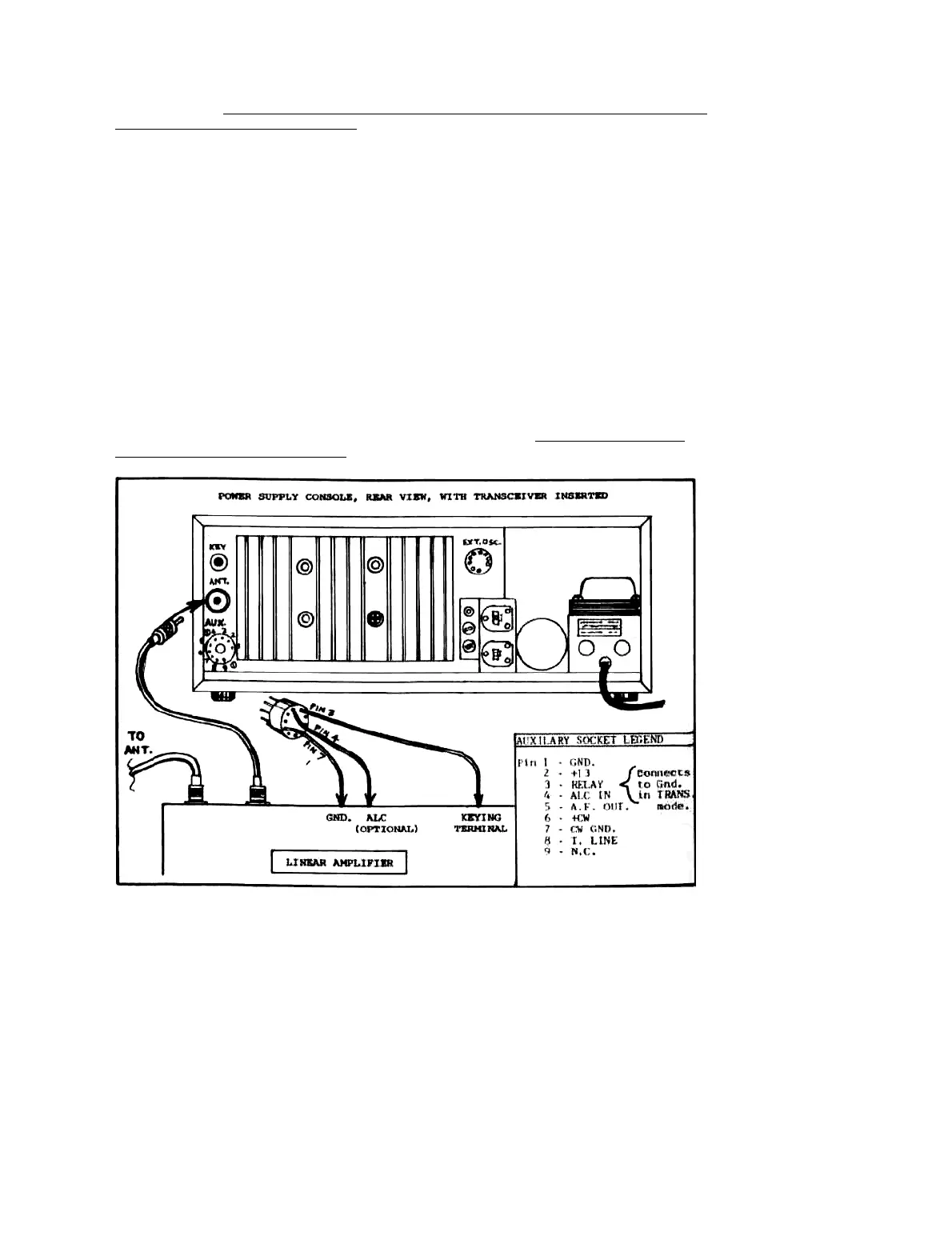
Figure 2-2. Linear Amplifier Connections to ATLAS Transceiver
10
 Loading...