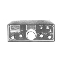
4-18. PC-820 100 kHz Crystal Calibrator
The 100 kHz crystal calibrator circuit is assembled on PC-820. Its schematic diagram is shown in Figure 4-11A. It
is actuated by the function switch in the "CAL" position. Frequency is adjusted by trimmer C821 against a known
standard such as WWV. Harmonics of the 100 kHz calibrator may be coupled out of the transceiver from the
antenna connector into another receiver which is tuned to WWV or another known standard. C821 should then be
adjusted to zero beat with the standard signal. Output from PC-820 is coupled through C824 to the input terminal
of PC-800C, and its harmonics will be received at the 100 kHz increments on each band.
PC-820 VOLTAGE CHART, Function Switch in "CAL." position.
Q821
Q822
Base
Base
-3.4
Collector
+4
Collector
+6
Emitter
0
Emitter
0
PC-820 CIRCUIT COMPONENTS
C821.......
....……………. 5-30 pF Trimmer
C822.......
. . . ……. 300 pF 5% Silver Mica
C823.......
....... …………...01 MF l00vDisc
C824.......
......…………… 2.2 pF 10% Disc
R821.823. . . .
....………… 100K 10% 1/4 Watt
R822.824. . . .
...... …………10K 10% 1/4 Watt
Q821.822 ....
. . . …….. . MPS 3693 Transistor
X821.......
.......……………… 100 Khz Xtal
Figure 4-11. PC-820 Crystal Calibrator Schematic
41
 Loading...