affect the transceiver connections, and the danger of intermittant transient voltage spikes will be reduced.
If drilling and tapping the battery posts is not practical, then connect the leads to the engine end of the battery
cables. The negative cable will usually be found going to a bolt on the engine block, while the positive cable
usually goes to a bolt on the starter solenoid. Use proper terminal lugs at these points for connecting the leads. The
red lead goes to positive and the brown lead to negative. (If power cable has black and white leads, the black is
negative, and the white is positive). A protective diode is built into the transceiver plug, and will open if polarity is
inadvertantly connected wrong. As discussed in paragraph 2-4, the battery clamps should be cleaned and
tightened. All electrical connections should likewise be checked and tightened.
2-26 INSTALLATION OF 25 AMP CIRCUIT BREAKER. The 25 ampere circuit breaker supplied with the kit
should be installed in series with the positive lead. It is best to mount it close to the battery end of the cable, at
some convenient place on the side of a metal panel or bracket. Short metal screws are supplied for this purpose. It
is not important that the metal case of the circuit breaker be grounded, since there are no connections made to the
case. Cut the positive red (or white) power lead, install No. 10 terminal lugs, and secure firmly to the circuit
breaker with washers and nuts. Solder the terminal lugs.
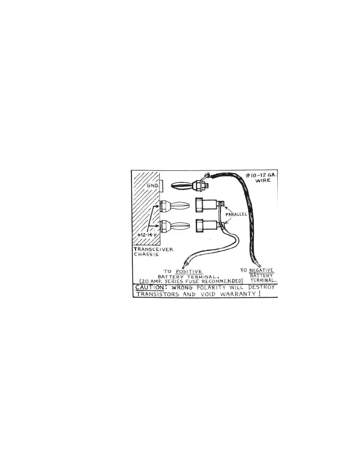
2-27. OTHER D.C. INSTALLATIONS. In the event that you have not purchased the DMK, MBK, or DCC kits,
your transceiver comes with two banana jacks for the positive battery lead, and are to be connected in parallel as
shown in Figure 2-5. The banana plug connects to the negative battery lead. The battery leads should be of No. 10
or No. 12 gauge stranded wire of the automotive type. A 20 amp. fuse or circuit breaker should be installed in the
positive lead. Figure 2-5 illustrates the proper connections required between the battery and the Atlas transceiver.
CAUTION IT IS EXTREMELY IMPORTANT THAT PROPER
POLARITY BE OBSERVED. THE POSITIVE BATTERY LEAD MUST GO TO THE TWO TERMINALS CLEARLY
MARKED ON BACK OF THE TRANSCEIVER. THE NEGATIVE BATTERY LEAD MUST GO TO THE
TRANSCEIVER CHASSIS GROUND, AND THE BANANA PLUG IS FOR THIS PURPOSE. EVEN MOMENTARY
CONNECTION OF THE WRONG POLARITY WILL DESTROY THE TRANSISTORS, AND VOID THE ATLAS
WARRANTY.
Figure 2-5. D.C. Power Connections
12
 Loading...