Section 5
4-19 PC-900C Transmitter Input Tuning .....…………………………………………............ 42
4-20 PC-1010/1020 Low Pass Filters ...................…………………………………………… 44
4-21 PC-1100A SWR Bridge, Antenna Relay ..............……………………………………… 46
ACCESSORIES .................................... ………………………………………………………47
5-1 Model PC-120 Noise Blanker ....................... ……………………………………………47
5-2 Model l0x Crystal Oscillator ....................... ……………………………………………...49
5-4 Model VX-5 VOX .............................. ……………………………………………………52
5-5 Model DD-6 Digital Dial .......................... ……………………………………………….52
LIST OF ILLUSTRATIONS
Figure
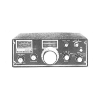
1-1 Atlas Model 21 Ox Illustrated with Optional 220-CS AC Console ......... 1
Remote CW Transmit Switch for Atlas Transceivers
Linear Amplifier connections for Atlas Transceivers
In Mobile Mounting Kit Installation
Mobile Bracket Kit Installation ......................
D.C. Power Connections ..........................
PS Schematic Diagram ...............
Front Panel of ATLAS 210x ........................
Rear Panel of ATLAS 210x/215x ....................
ATLAS 210x/215x Modular Design and Plug
ATLAS 210x/215x Block Diagram ...................
Crystal Ladder Filter Selectivity Characteristics ...........
100C Schematic Diagram ........................
200C Schematic Diagram ........................
300C Schematic Diagram ........................
500D/520A Schematic Diagram ...................
400C Schematic Diagram ...............
400C Schematic (tuning section only) .......
600 Schematic Diagram .........................
800C/1200 Scliematic Diagram ...........
8000/1200 Schematic Diagram ...........
820 Crystal Calibrator Schematic Diagram
9000 Transmitter Input Tuning Schematic Diagram ......
1010/1020 low Pass Filter Schematic Diagram .........
SWR Bridge, Antenna Relay Scliematic Diagram . . .
120 Noise Blanker Schematic Diagram ...............
Model l0x Crystal Oscillator ........................
Model 10X Crystal Oscillator Schematic Diagram
1 Transformer installation
6 Digital Dial ...........................
5-6 Model 210x/215x Chassis Wiring ..................... inside back cover

 Loading...