7
12 12
$$
$
7
7
7/
/
/
t
*
1
/
ཆ
᧕
⭥
Ⓚ
᤹䫞ᔰޣ
᤹䫞ᔰޣ
9
.0
46
/1
6%83
.0
$
$
ཆ
᧕
⭥
Ⓚ
/
1
*
t
᤹䫞ᔰޣ
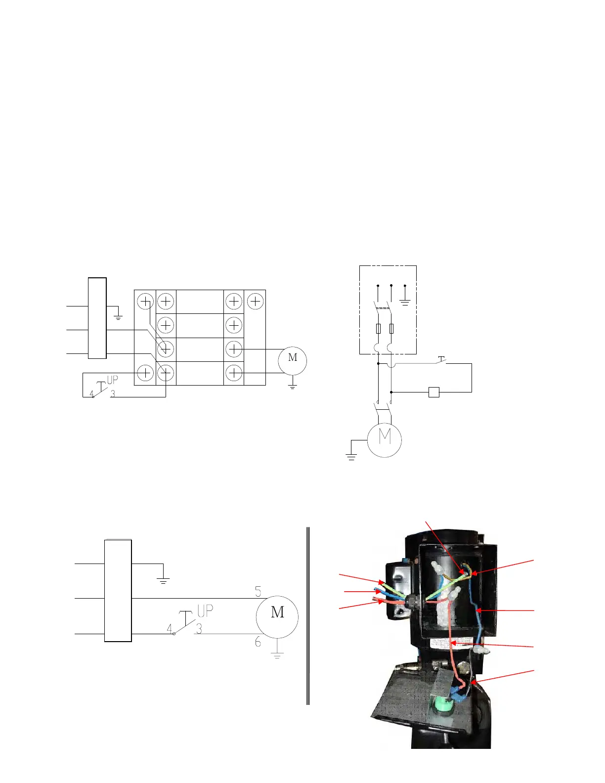
D. Install Electric System
Refer to electric schenatic diagram, connect the power supply according to the
requirement of motor nameplate. Note: The lift must be good grounding and pay
attention to the direction of motor rotation when using 380V motor.
PEAK Wire connection for single phase hydraulic power unit motor (Fig.8)
1. Power supply wires (Live wire L and Zero wire N) connected with the two wires on
A.C.contactor terminal marked L1ǃL2 respectively.
2. Two wires on hydraulic power unit motor connected with A.C.contactor terminal marked
T1ǃT2 respectively.
3. A.C. contactor A2 connected with L2.
4. Two wire on button switch connected with A.C. contactor terninal marked A1ǃL1.
SPX Wire connection for single phase
hydraulic power unit motor(See Fig.9)
ˊ
Power supply live wire L connected with button switch wire 4ʿ.
ˊ
Button switch wire 3ʿconnected with motor wire 6#.
ˊ
Motor wire 5# connected with power supply zero wire (N).
A.C. connector
Electric schematic diagram
PEAK hydraulic power unit motor wiring
Fig.8
Connected with
earth wire
ƻ
6
ƻ
5
ƻ
3
ƻ
4
Spx Wire connection for single phase
hydraulic power unit motor Fig.9
P
O
W
E
R
Push button
Push button
P
O
W
E
R
Push button
 Loading...