8
*
᤹䫞ᔰޣ
$$
$
7
7
7
1212
/
/
/
t
/
/
/
ཆ
᧕
⭥
Ⓚ
.0
6%83
///
46
.0
9
᤹䫞ᔰޣ
$ $
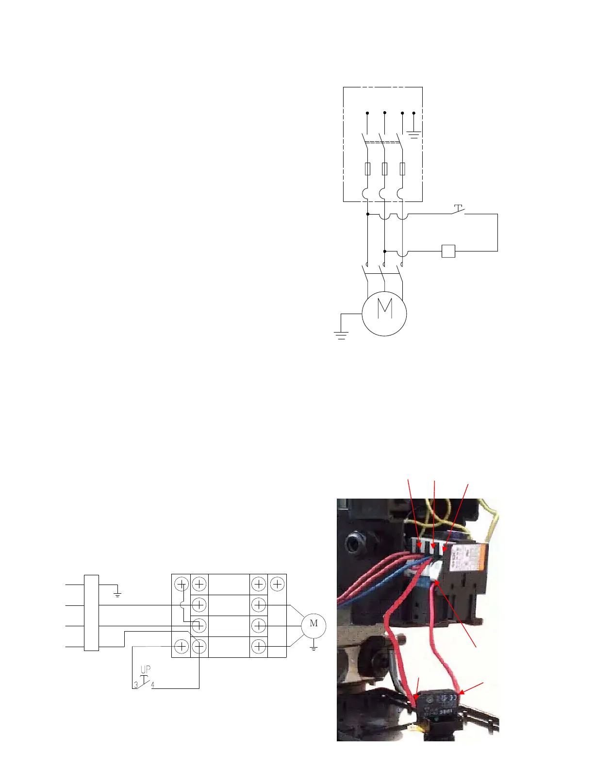
Wire connection for three phase hydraulic power unit motor
1. Electric schematic diagram
(See Fig.10)
2. Steps for connection (See Fig.11)
ƻ
1 ǃThree Power supply wires marked (L1ǃL2ǃL3) connected with A.C.contactor terminal
marked L1ǃL2ǃL3 respectively.
ƻ
2 ǃA.C. contactor terminal marked L1connected with button switch terminal marked 4#, L2
connected with A2, terminal marked A1 connected with button switch terminal
marked 3#.
A1
3#
4#
L1
L2
L3
Fig.10
Connection diagram
Fig. 11
Push button
Push button
 Loading...