Common Features Description
Atmel 8051 Microcontrollers Hardware Manual 2-84
4316B–8051–02/04
Reset Value = 0000 0000b
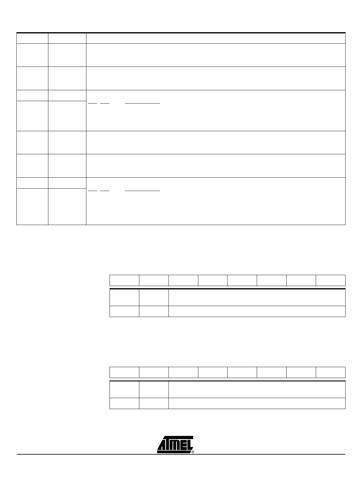
Table 2-4. TH0 Register - TH0 (S:8Ch)
Timer 0 High Byte Register.
Reset Value = 0000 0000b
Table 2-5. TL0 Register - TL0 (S:8Ah)
Timer 0 Low Byte Register
Reset Value = 0000 0000b
Bit Number Bit Mnemonic Description
7GATE1
Timer 1 Gating Control Bit
Clear to enable timer 1 whenever the TR1 bit is set.
Set to enable timer 1 only while the INT1# pin is high and TR1 bit is set.
6C/T1#
Timer 1 Counter/Timer Select Bit
Clear for timer operation: timer 1 counts the divided-down system clock.
Set for Counter operation: timer 1 counts negative transitions on external pin T1.
5M11Timer 1 Mode Select Bits
M11
M01 Operating mode
0 0 Mode 0: 8-bit timer/counter (TH1) with 5-bit prescaler (TL1).
0 1 Mode 1: 16-bit timer/counter.
1 0 Mode 2: 8-bit auto-reload timer/counter (TL1). Reloaded from TH1 at overflow.
1 1 Mode 3: timer 1 halted. Retains count.
4M01
3GATE0
Timer 0 Gating Control Bit
Clear to enable timer 0 whenever the TR0 bit is set.
Set to enable timer/counter 0 only while the INT0# pin is high and the TR0 bit is set.
2C/T0#
Timer 0 Counter/Timer Select Bit
Clear for timer operation: timer 0 counts the divided-down system clock.
Set for counter operation: timer 0 counts negative transitions on external pin T0.
1M10Timer 0 Mode Select Bit
M10
M00 Operating mode
0 0 Mode 0: 8-bit timer/counter (TH0) with 5-bit prescaler (TL0).
0 1 Mode 1: 16-bit timer/counter.
1 0 Mode 2: 8-bit auto-reload timer/counter (TL0). Reloaded from TH0 at overflow.
1 1 Mode 3: TL0 is an 8-bit timer/counter.
TH0 is an 8-bit timer using timer 1’s TR0 and TF0 bits.
0M00
76543210
Bit
Number
Bit
Mnemonic Description
7:0 High Byte of Timer 0.
76543210
Bit
Number
Bit
Mnemonic Description
7:0 Low Byte of Timer 0.