Common Features Description
2-101 Atmel 8051 Microcontrollers Hardware Manual
4316B–8051–02/04
2.14 Framing Error
Detection
Framing bit error detection is provided for the three asynchronous modes (modes 1, 2
and 3). To enable the framing bit error detection feature, set SMOD0 bit in PCON regis-
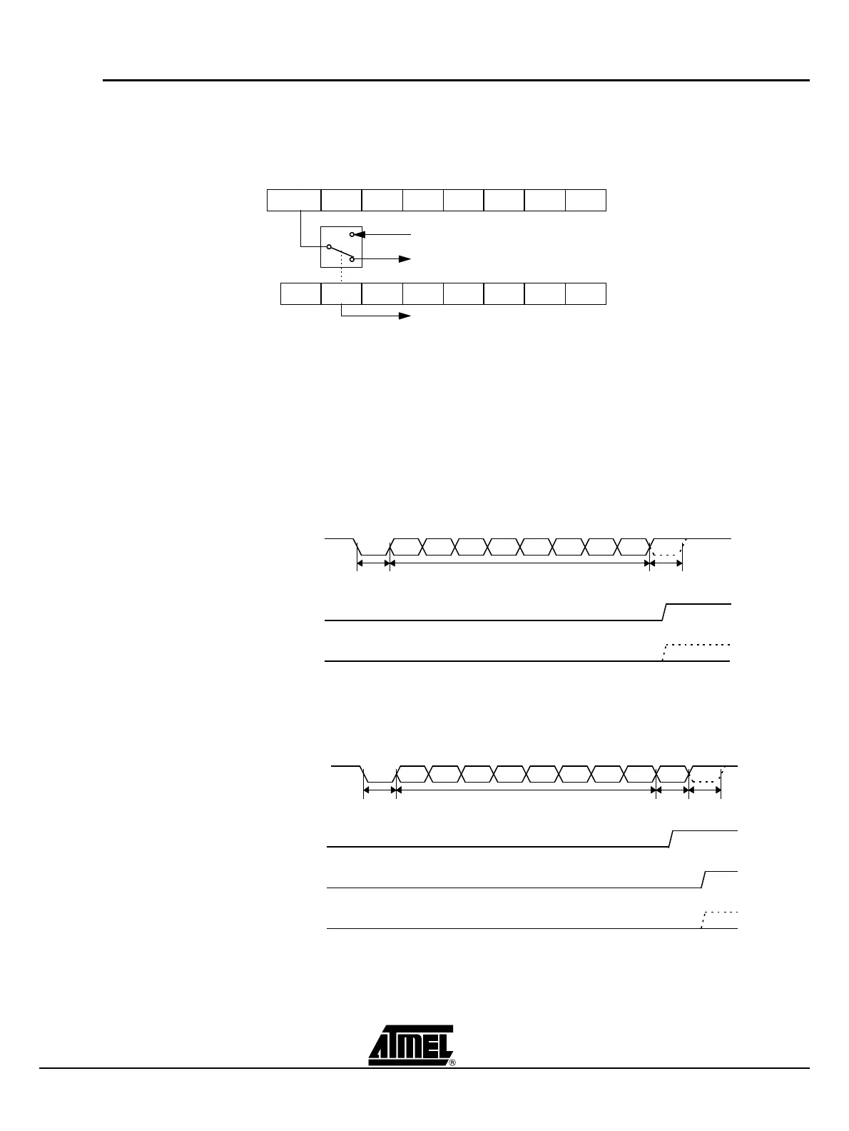
ter (see Figure 2-25).
Figure 2-25. Framing Error Block Diagram
When this feature is enabled, the receiver checks each incoming data frame for a valid
stop bit. An invalid stop bit may result from noise on the serial lines or from simultaneous
transmission by two CPUs. If a valid stop bit is not found, the Framing Error bit (FE) in
SCON register (see Table 2-17) bit is set.
Software may examine FE bit after each reception to check for data errors. Once set,
only software or a reset can clear FE bit. Subsequently received frames with valid stop
bits cannot clear FE bit. When FE feature is enabled, RI rises on stop bit instead of the
last data bit (see Figure 2-26 and Figure 2-27).
Figure 2-26. UART Timings in Mode 1
Figure 2-27. UART Timings in Modes 2 and 3
RITIRB8TB8RENSM2SM1SM0/FE
IDLPDGF0GF1POF-
SMOD0
SMOD
To UART framing error control
SM0 to UART mode control (SMOD0 = 0)
Set FE bit if stop bit is 0 (framing error) (SMOD0 = 1)
SCON (98h)
PCON (87h)
Data byte
RI
SMOD0=X
Stop
bit
Start
bit
RXD
D7D6D5D4D3D2D1D0
FE
SMOD0=1
RI
SMOD0=0
Data byte Ninth
bit
Stop
bit
Start
bit
RXD
D8D7D6D5D4D3D2D1D0
RI
SMOD0=1
FE
SMOD0=1
 Loading...


