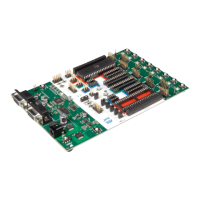
Hardware Description
2-7 AT89STK-11 Hardware User Guide
7676B–8051–08/07
2.5 Features
This section presents the various features such as leds, buttons, etc... available on the
board.
2.5.1 Push-Buttons RESET can be used to apply warm reset to the MCU
ISP can be used with RESET to apply hardware conditions resulting in bootloader
start
INT0 push-button can be used to activate INT0 input
INT1 push-button can be used to activate INT1 input
2.5.2 User Push buttons PB0, PB1, PB2 and PB3 are four push-buttons available for user application
They are made available on a 6 pins socket and in the expansion area so user can use
them according to the application needs.
2.5.3 Indicator LEDs PWR led is driven by input of voltage regulator
Rx led is connected to Rx of UART MCU (SP3 jumper can be soldered or not)
Tx led is connected to Tx of UART MCU (SP4 jumper can be soldered or not)
ALE led is connected to ALE of MCU
2.5.4 User LEDs LED0, LED1, ... LED7 are height leds available for user application
They are made available on a 10 pins socket and in the expansion area so user can use
them according to its application needs.
2.5.5 Ports Port 0 and Port 2 are made available on two 10 pins sockets to ease user interconnec-
tion to the MCU.
The are also available on the expansion area.
2.5.6 Clocks An external clock can be connected to the board to control externally XTAL1 input clock
of MCU by using the XTAL1 from the expansion area.
In the same way, another external clock can be connected to control externally the PCA
clock (P1.2/ECI).
2.6 Interfaces
2.6.1 TWI The TWI connector is controlled by hardware TWI I/O of MCU (for Product including this
feature). The signals sda and scl are controlled by the TWI ports of MCU.
This TWI bus is also connected to the expansion area.
External TWI pull-ups are not provided on the AT89STK-11.
2.6.2 SPI The SPI connector is directly connected to SPI I/O of the MCU.
2.6.3 RS-232 The DB9 connector is connected to on-chip UART peripheral through a standard RS232
driver/receiver. Two leds are provided to indicate activity on Rx and Tx lines (They can
be disconnected removing solder pad SP3 and SP4).
2.6.4 OCD The On-Chip Debug interface (OCD) is provided on a 6-pin connector.
 Loading...