EasyManua.ls Logo

Atmel AVR STK500 - User Manual

Atmel AVR STK500
62 pages
Print Icon
To Next Page IconTo Next Page
Loading...
STK500
..............................................................................................
User Guide

Questions and Answers

  • Y
    yhowellAug 17, 2025
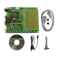
    What to do if the Atmel AVR STK500 Controller AVR device cannot be programmed?
    • M
      mary14Aug 17, 2025
      If the Atmel Controller AVR device cannot be programmed, check the following: * Ensure the PC serial cable is connected to the PC COM port and the RS232 PROG port. * Verify the AVR device is inserted in the correct socket with the correct orientation, matching the notch on the AVR socket with the notch on the AVR device. * Confirm the target ISP header is connected using the 6-pin flexible cable from the ISP6PIN header to the correct SPROG target ISP header. * Make sure the jumper settings are set to the default setup. * If the memory lock bits are programmed, erase the memory before programming.
  • E
    Elizabeth BrownAug 20, 2025
    Why AVR Studio does not detect Atmel Controller STK500?
    • C
      Cassie RobertsAug 20, 2025
      If AVR Studio isn't detecting your Atmel Controller STK500, here are a few things to check: * Make sure the serial cable is connected to RS232 PROG and verify the power connections. * Disable any other programs that might be using the PC COM port. * Try changing the PC COM port. * In AVR Studio, disable COM port auto-detection in the file menu and manually set the COM port to the correct one.
  • L
    Lauren JonesAug 22, 2025
    How to fix the Atmel AVR STK500 Controller when the red power LED is not on?
    • J
      John GonzalezAug 22, 2025
      If the red power LED on your Atmel Controller is not on, consider these possible causes and solutions: * Ensure the DC power cable is connected to the DC jack. * Verify that you are using the correct power supply: a DC type 10-15V, min. 500mA. * Check that the power switch is turned on.
  • X
    xespinozaAug 25, 2025
    What to do if the preprogrammed example code does not toggle the LEDs on the Atmel Controller?
    • M
      Marcus BellAug 26, 2025
      If the preprogrammed example code isn't toggling the LEDs on your Atmel Controller, check the following: * Ensure that the AVR device is plugged into the correct socket. * Verify that the LEDs are connected to the PORTD header and the SWITCHES header is connected to the PORTB header. * If the Flash memory is erased, connect the STK500 to a PC and reprogram the AVR device.
  • J
    Joy HamiltonAug 27, 2025
    Why is the status LED blinking quickly on my Atmel Controller?
    • J
      Jasmin WilliamsAug 28, 2025
      If the status LED on your Atmel Controller is blinking quickly, it could be due to: * A short circuit on VTARGET: Resolve the short circuit. * An external VTARGET being used and turned off: Set VTARGET to a value below 0.3V in AVR Studio.
  • J
    jasminefletcherAug 30, 2025
    What does it mean if the status LED is blinking slowly on the Atmel AVR STK500 Controller?
    • H
      Henry MullinsAug 30, 2025
      If the status LED is blinking slowly on your Atmel Controller, it indicates a short circuit on AREF. Resolve the short circuit.
  • J
    Jill RussoSep 2, 2025
    Why don't the LEDs work on the Atmel AVR STK500 Controller when running from external VTARGET?
    • A
      albert73Sep 2, 2025
      If the LEDs aren't working when running from an external VTARGET, ensure that the STK500 is powered and turned on, as it must be powered for the LEDs to function.
  • C
    chowellSep 5, 2025
    Why is the red power LED not on for my Atmel Motherboard?
    • J
      Joseph LewisSep 5, 2025
      The red power LED might not be on because the DC power cable isn't connected; in this case, connect the DC power cable to the DC jack. Another reason could be the wrong power supply; ensure you're using a DC type 10-15V power supply with a minimum of 500mA. Finally, check if the power switch is turned off and turn it on.
  • T
    Tyler ThompsonSep 7, 2025
    What to do if the Atmel Motherboard AVR device cannot be programmed?
    • H
      Holly ValdezSep 7, 2025
      If the AVR device cannot be programmed, possible causes include: a disconnected PC serial cable (connect the serial cable to the PC COM port and the RS232PROG port), the AVR device being inserted in the wrong socket (ensure the correct socket is used), or incorrect AVR device orientation (verify the notch on the AVR socket matches the notch on the AVR device). Other potential issues are: the target ISP header not connected (connect the 6-pin flexible cable from the ISP6PIN header to the correct SPROG target ISP header), wrong jumper settings (set jumper to default setup), a VTARGET voltage that is too low (check the AVR datasheet for minimum operating voltage), or programmed memory lock bits (erase the memory before programming).
  • R
    Robert IbarraSep 12, 2025
    How to fix 'AVR Studio does not detect STK500' on Atmel Motherboard?
    • K
      Kenneth PhillipsSep 12, 2025
      If AVR Studio doesn't detect STK500, check that the serial cable is connected to RS232PROG and that the power connections are correct. Also, another program might be using the PC COM port; disable any such programs. If AVR Studio doesn't detect the COM port, disable COM port auto-detection in the AVR Studio file menu and manually force the COM port to the correct one.

Summary

Section 1 Introduction

1.1 Starter Kit Features

Overview of the AVR STK500 starter kit's capabilities and components.

1.2 Device Support

Lists the AVR devices compatible with the STK500 starter kit.

Section 2 Getting Started

2.1 Unpacking the System

Details the contents of the STK500 starter kit package.

2.2 System Requirements

Specifies the minimum hardware and software needed for STK500 operation.

2.3 Quick Start

Provides initial steps to set up and test the STK500 starter kit.

2.3.1 Connecting the Hardware

Instructions for physically connecting the STK500 to a PC and target device.

2.3.2 Programming the Target AVR Device

Guide to programming an AVR device using AVR Studio and the STK500.

Section 3 Hardware Description

3.1 Description of User LEDs

Explains the function and implementation of the user-accessible LEDs.

3.2 Description of User Switches

Details the function and implementation of the user-accessible push-button switches.

3.3 Connection of LEDs and Switches

Shows how to connect LEDs and switches to I/O port headers for use.

3.4 Port Connectors

Describes the pinouts and connections for the general I/O port headers.

3.5 Description of User RS-232 Interface

Explains the two RS-232 ports on the STK500 and their usage.

3.6 Description of DataFlash Pins

Details the pins and connections related to the DataFlash memory interface.

3.7 Target Socket Section

Overview of the sockets for inserting target AVR devices for programming and operation.

3.7.1 ISP Programming

Explains In-System Programming (ISP) using the STK500.

3.7.2 High-voltage Programming

Describes the High-voltage Programming method for AVR devices.

3.8 Jumper Settings

Explains the function and default settings of various jumpers on the STK500.

3.8.1 Target Vcc Settings, VTARGET

Details how to set and control the target device's supply voltage (VTARGET).

3.8.2 Analog Reference Voltage, AREF

Explains the control and usage of the analog reference voltage (AREF).

3.8.3 Reset Settings, RESET

Describes how the RESET jumper controls the target AVR's reset signal.

3.8.4 Clock Settings, XTAL1 and OSCSEL

Explains how to configure clock sources and settings using jumpers.

3.9 Expansion Connectors

Information on expansion connectors for prototyping and additional modules.

3.10 Prog Ctrl and Prog Data Headers

Details the headers used for parallel High-voltage Programming.

3.11 Miscellaneous

Covers additional features like push buttons and status LEDs.

3.11.1 RESET Push Button

Explains the function of the RESET push button.

3.11.2 PROGRAM Push Button

Describes the PROGRAM push button's role in microcontroller upgrades.

3.11.5 Status LED

Explains the multi-color status LED and its indications.

Section 4 Installing AVR Studio

Installing AVR Studio

Step-by-step instructions for installing the AVR Studio software.

Section 5 Using AVR Studio

5.1 Windows Software

Overview of the supporting software for STK500 within AVR Studio.

5.2 Starting the Windows Software

Instructions on how to launch and start AVR Studio and the STK500 interface.

5.3 STK500 User Interface

Detailed explanation of the various tabs and settings within the STK500 interface.

5.3.1 Program Settings

Configuration options for programming Flash and EEPROM memory.

5.3.2 Fuses Settings

How to read and write fuse bits for device configuration.

5.3.3 LockBits Settings

Management of device lock bits for protection and security.

5.3.4 Advanced Settings

Accessing advanced device features like signature bytes and oscillator calibration.

5.3.5 Board Settings

Adjusting board-level operating conditions like VTARGET and AREF.

5.3.6 Auto Settings

Automating programming sequences for multiple devices.

5.3.7 History Window

Reviewing the communication log between AVR Studio and STK500.

5.4 Command Line Software

Using STK500 through DOS commands for automated programming.

Section 6 In-System Programming of an External Target System

In-System Programming of an External Target System

Using STK500 to program AVR devices on external target boards.

Section 7 Troubleshooting Guide

Troubleshooting Guide

Common problems and their solutions for STK500 operation.

Section 8 Technical Support

Technical Support

Information on how to obtain technical assistance for the STK500.

Section 9 Example Applications

9.1 Using LEDs and Switches

A practical example demonstrating the use of LEDs and switches with AVR code.

Section 10 Appendix A

Appendix A

Contains supplementary information, including a block diagram.

Atmel AVR STK500 Specifications

General IconGeneral
BrandAtmel
ModelAVR STK500
CategoryController
LanguageEnglish

Related product manuals