Using AVR Studio
5-4 AVR STK500 User Guide
1925C–AVR–3/03
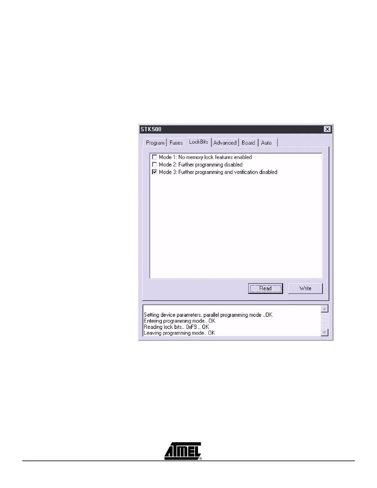
5.3.3 “LockBits” Settings Similar to the “Fuses” tab, the “LockBits” tab shows which lock modes are applicable to
the selected device. All lock bits are accessible in both ISP and High-voltage Program-
ming. A lock mode may consist of a combination of setting multiple Lock bits. This is
handled by the STK500 user interface, and the correct lock bits are programmed auto-
matically for the selected lock mode. Once a Lock mode protection level is enabled, it is
not possible to lower the protection level by selecting a “lower” degree of protection or
by setting a different Lock mode. The only way to remove a programmed Lock bit is to
perform a complete chip erase, erasing both program and data memories. One excep-
tion exists: If the target device has a programmed “EESAVE” fuse, the contents of the
EEPROM will be saved even though a complete chip erase on the device is performed.
Figure 5-4. LockBits
5.3.4 “Advanced”
Settings
The “Advanced” tab is currently divided into two subgroups.
5.3.4.1 Signature Bytes By pressing the “Read Signature” button, the signature bytes are read from the target
device. The signature bytes act like an identifier for the part. After reading the signature,
the software will check if it is the correct signature according to the chosen device.
Please refer to the AVR datasheets to read more about signature bytes.
 Loading...