Hardware Description
3-20 AVR STK500 User Guide
1925C–AVR–3/03
When connected to an external system, there is often an external pull-up resistor con-
nected to the reset line. A typical reset connection is shown in Figure 3-27.
Figure 3-27. External Reset Connection
If the external pull-up resistor is too low (<4.7 kΩ), STK500 will not be able to pull the
RESET line low.
3.8.4 Clock Settings,
XTAL1 and OSCSEL
STK500 includes several clock options for the target AVR. Setting the jumpers XTAL1
and OSCSEL controls the clock selections. OSCSEL determines what signal to route to
the XTAL1 pin of the AVR.
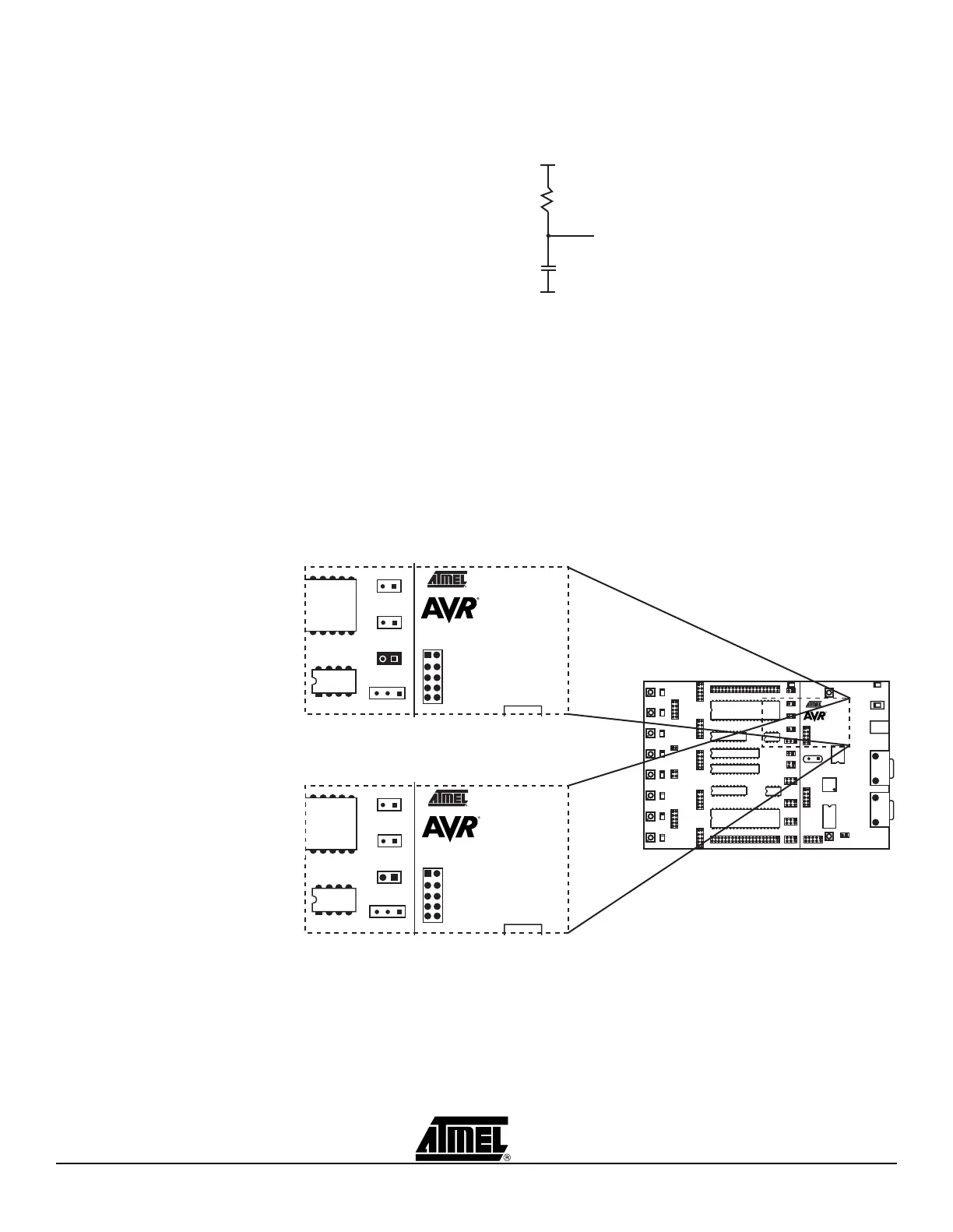
When the XTAL1 jumper is connected, the STK500 internal clock system is used as
main clock to the target AVR. When XTAL1 jumper is not mounted, the internal clock
system is disconnected. This allows external clock signals or crystals to be used as tar-
get clock source for the AVR. Figure 3-28 illustrates the XTAL1 jumper option.
Figure 3-28. XTAL1 Jumper Options
When the XTAL1 jumper is not mounted, an external clock source or crystal can be con-
nected to the PORTE header. This is shown in Figure 3-30.
R (4.7 kohm)
C (10 nF)
RESET
AREF
RESET
XTAL1
OSCSEL
Jumper Mounted
On-board XTAL1 Signal Connected (Default)
AREF
RESET
XTAL1
OSCSEL
Jumper not Mounted
On-board XTAL1 Signal Disconnected
 Loading...