AVR STK500 User Guide 3-1
Rev. 1925C–AVR–3/03
Section 3
Hardware Description
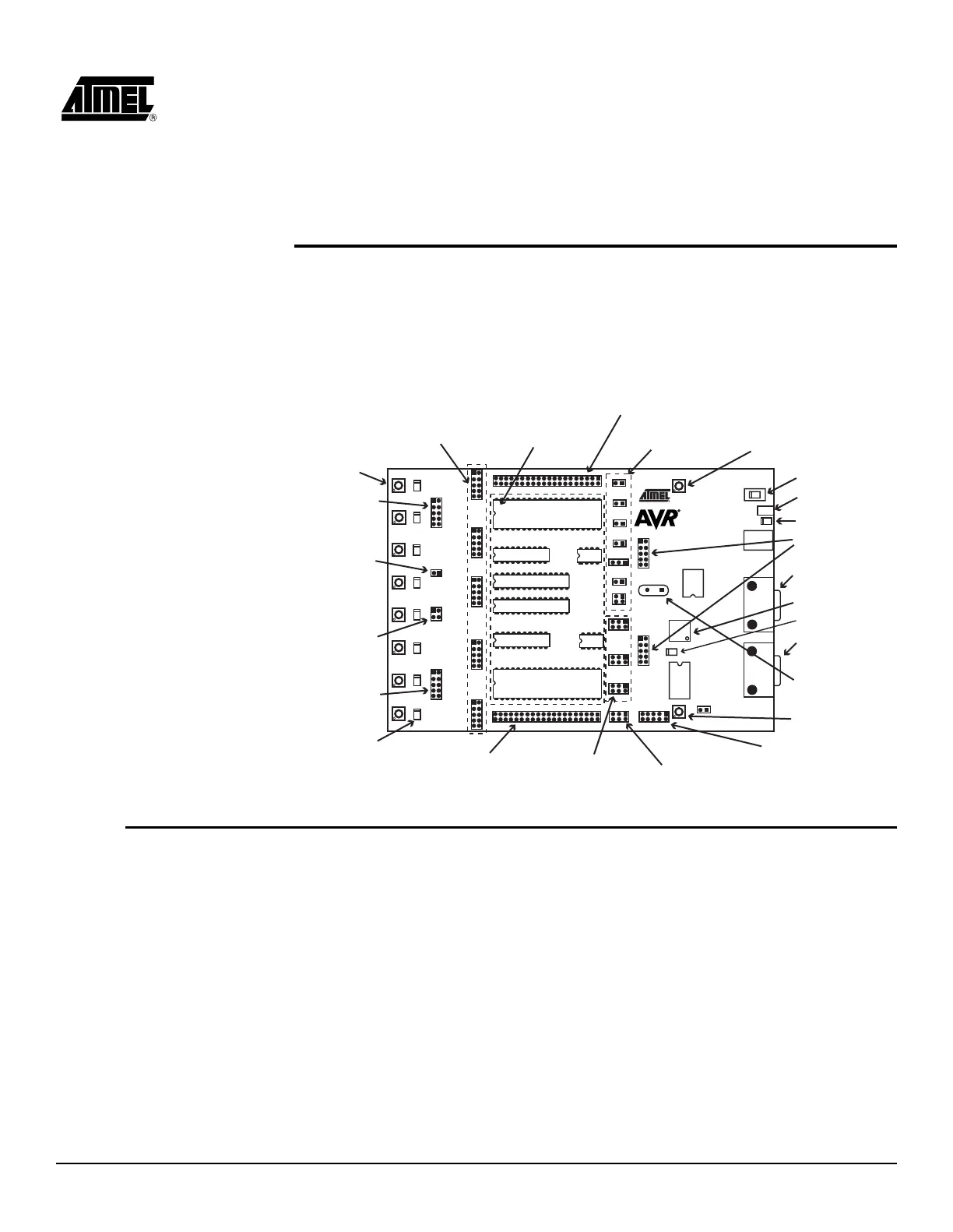
Figure 3-1. STK500 Components
3.1 Description of
User LEDs
The STK500 starter kit includes 8 yellow LEDs and 8 push-button switches. The LEDs
and switches are connected to debug headers that are separated from the rest of the
board. They can be connected to the AVR devices with the supplied 10-wire cable to the
pin header of the AVR I/O ports. Figure 3-4 shows how the LEDs and switches can be
connected to the I/O port headers. The cables should be connected directly from the
port header to the LED or switch header. The cable should not be twisted. A red wire on
the cable indicates pin 1. Confirm that this is connected to pin 1 on each of the headers.
Figure 3-2 shows how the LED control is implemented. This solution will give the same
amount of light from the LED for all target voltages from 1.8V to 6.0V.
Power Switch
Power Connector
Power LED
Parallel Programming
Headers
RS-232 Port
for Programming
Master MCU
Status LED
RS-232 Port
for Communication
Options Setting
Jumpers
Sockets for
Target AVR
Headers
for I/O Ports
Switches
Header for
Switches
RS-232 Interface
Header
DataFlash Interface
Header
LEDs
Header for
Expansion Boards
Header for LEDs
10-pin ISP Header
(for External Target Only)
6-pin ISP Header
Target ISP Headers
Program Button
Socket for
Crystal
Target Reset
Push Button
Header for
Expansion Boards
 Loading...