Hardware Description
AVR STK500 User Guide 3-11
1925C–AVR–3/03
It is not necessary to remove the 6-wire cable from its ISP position while running a pro-
gram in the AVR. The port pins used for ISP programming can be used for other
purposes in your program.
3.7.2 High-voltage
Programming
For High-voltage Programming, a 12V programming voltage is applied to the RESET pin
of the AVR device. All AVR devices can be programmed with High-voltage Program-
ming, and the target device can be programmed while it is mounted in its socket.
Two different methods are used for High-voltage Programming: 8-pin parts use a serial
programming interface, while other parts use a parallel programming interface. The pro-
gramming signals are routed to the correct pins of the target device using the cables
supplied with STK500.
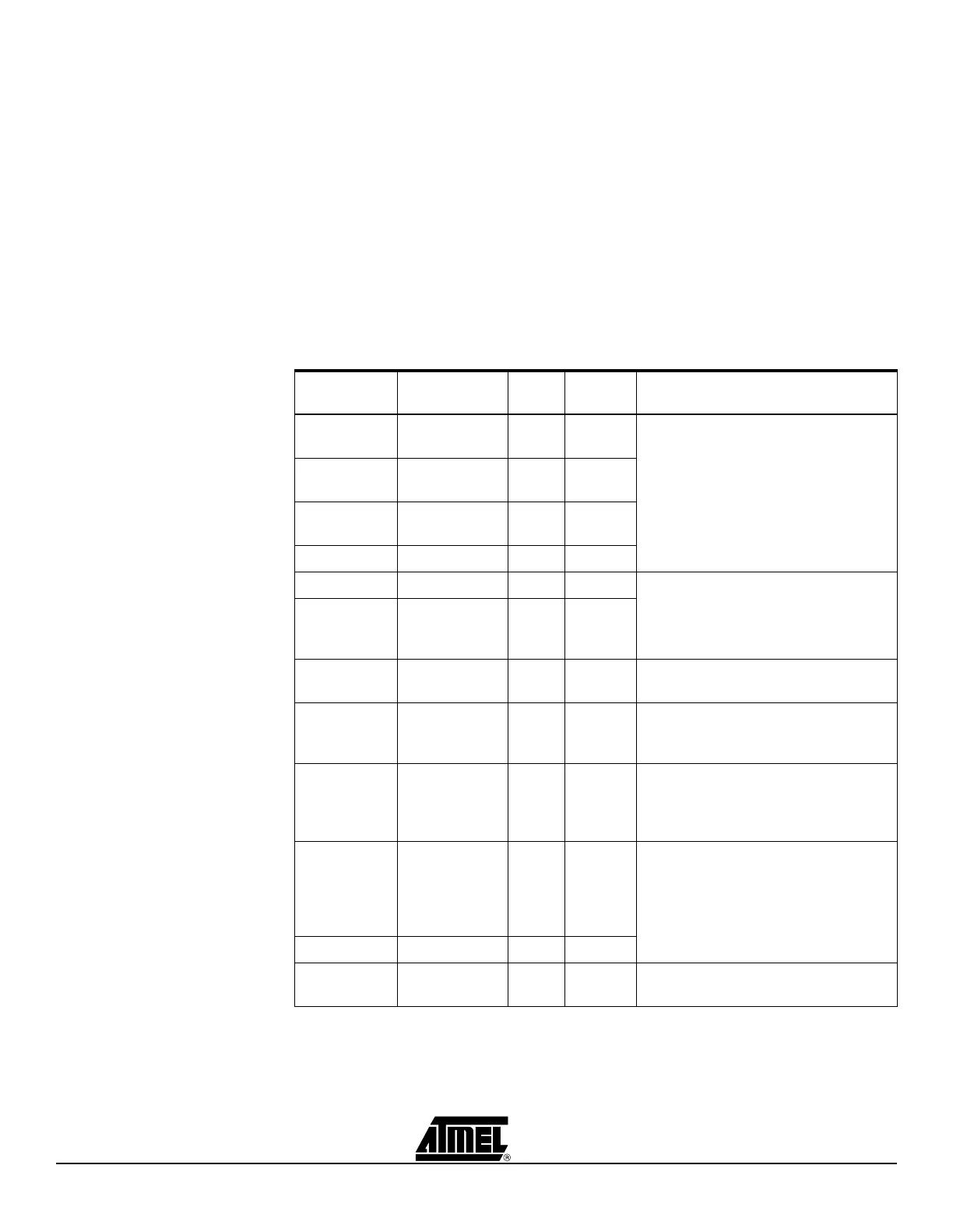
Table 3-3 summarizes the programming method and special considerations when using
High-voltage Programming.
Table 3-3. High-voltage Programming Settings
AVR
Devices
STK500
Socket Color Number High-voltage Programming Method
AT90S1200
AT90S2313
SCKT3300D3 Red 3 Parallel High-voltage Programming.
Connect PROG CTRL header to
PORTD and PROG DATA to PORTB,
as shown in Figure 3-17 on page 3-12.
AT90S4414
AT90S8515
SCKT3000D3 Red 3
AT90S4434
AT90S8535
SCKT3100A3 Red 3
ATtiny28 SCKT3500D- None –
ATmega161 SCKT3000D3 Red 3 Parallel programming as above; mount
BSEL2 jumper. See Section 3.8.
ATmega16
ATmega163
ATmega323
SCKT3100A3 Red 3
AT90S2333
AT90S4433
SCKT3200A2 Green 2 Parallel programming as above; mount
PJUMP jumpers. See Section 3.8.
ATmega103
ATmega128
Use the
STK501 Top
Module
– – Parallel programming as above; mount
BSEL2 jumper. See Section 3.8.
ATmega8 SCKT3200A2 Green 2 Parallel programming as above; Mount
PJUMP jumpers and mount BSEL2
terminal to PC2. See Section 3.8.5 and
Section 3.8.6.
AT90S2323
AT90S2343
AT t i ny 11
AT t i ny 12
AT t i ny 22
SCKT3400D1 Blue 1 Serial High-voltage Programming
ATtiny15 SCKT3600A1 Blue 1
N/A SCKT3700A1 Blue 1 Socket not in use in this version of
STK500
 Loading...