Hardware Description
3-12 AVR STK500 User Guide
1925C–AVR–3/03
3.7.2.1 Parallel High-voltage
Programming
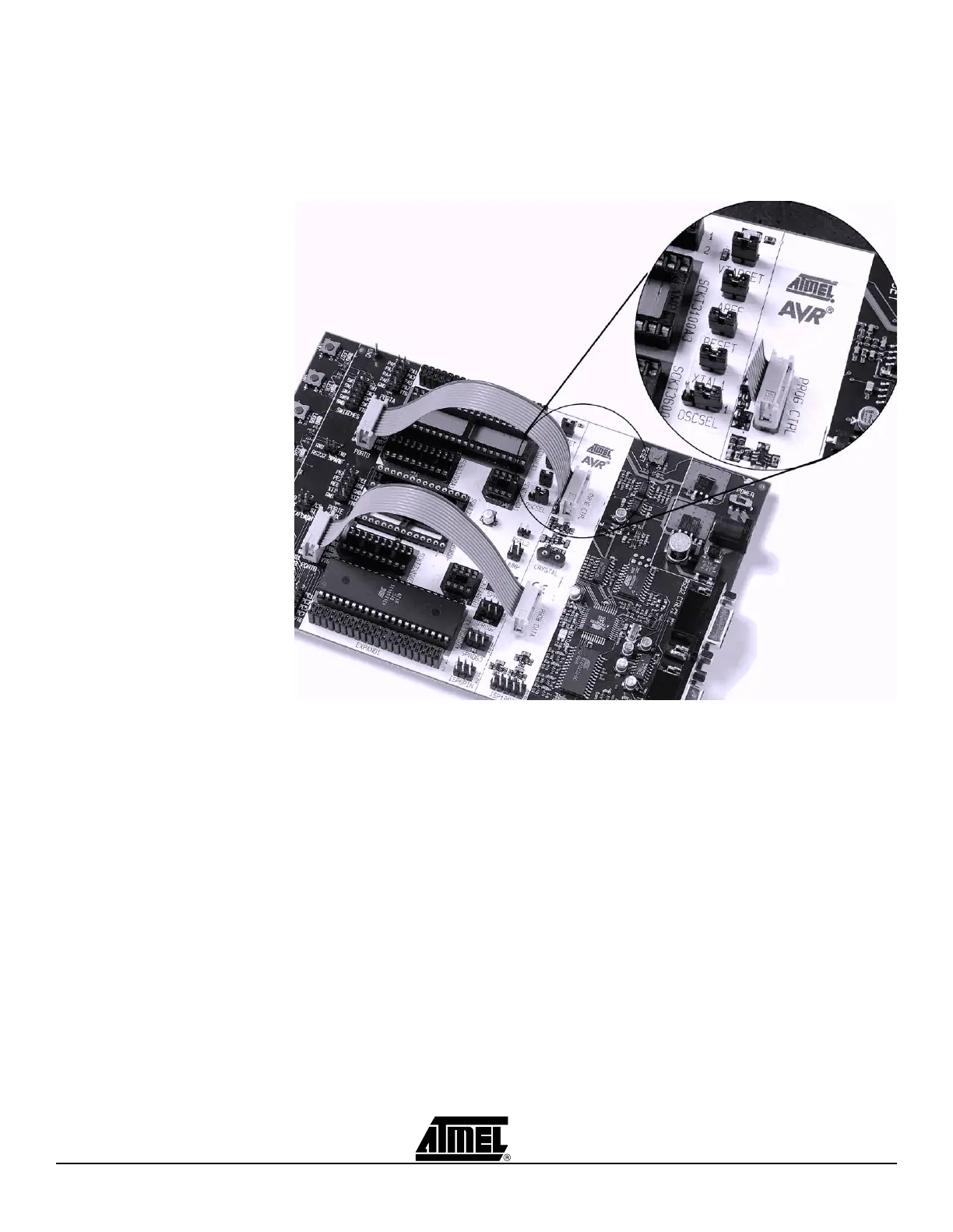
To use High-voltage Programming, the programming signal must be routed to the AVR
I/O pins. The two 10-wire cables supplied with the STK500 can be used to connect the
PROG DATA header to the PORTB header and the PROG CTRL header to the PORTD
header, as shown in Figure 3-17.
Figure 3-17. Connection for Parallel High-voltage Programming
Some of the jumper settings on STK500 must be changed when using High-voltage Pro-
gramming. Figure 3-18 explains these jumper settings.
 Loading...