Hardware Description
AVR STK500 User Guide 3-13
1925C–AVR–3/03
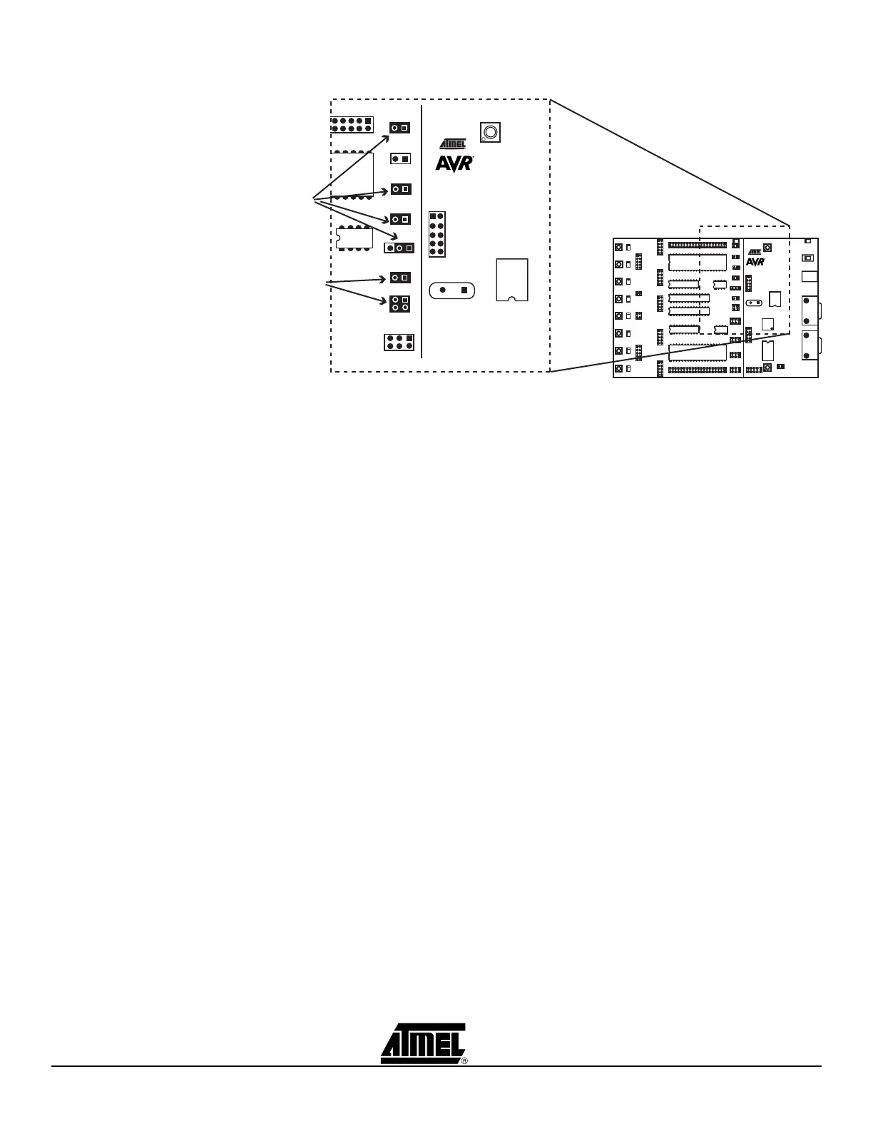
Figure 3-18. Jumper Settings for High-voltage Programming
Hardware setup for parallel High-voltage Programming:
1. Switch power off.
2. Place the device to program in its socket according to Table 3-3 on page 3-11.
3. Connect the headers PROGDATA and PORTB with the 10-wire cable.
4. Connect the headers PROGCTRL and PORTD with the 10-wire cable.
5. Mount jumper OSCSEL on pins 1 and 2 to select software-controlled clock.
6. Mount jumper XTAL1 to route the oscillator signal to the device.
7. Mount jumpers VTARGET and RESET.
8. When programming AT90S2333, AT90S4433, or ATmega8, mount both PJUMP
jumpers. The 2-wire cables can be used instead of jumpers.
9. When programming ATmega16, ATmega163, ATmega161, ATmega128, or
ATmega323, mount the BSEL2 jumper. When programming ATmega8, connect
BSEL2 terminal to PC2. A 2-wire cable can be used instead of jumpers.
10. Disconnect target system.
11. Switch power on.
12. Ensure that VTARGET is between 4.5V and 5.5V before programming. See Sec-
tion 5.3.5.1.
For a complete description of jumper settings, see Section 3.8, “Jumper Settings”.
Note: Remove the hardware setup for High-voltage Programming before starting a
debug session.
umpers
must be
Mounted
Device-
dependent
Jumpers
(See Below)
VTARGET
AREF
RESET
XTAL1
OSCSEL
BSEL2
PJUMP
 Loading...