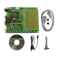
Hardware Description
3-14 AVR STK500 User Guide
1925C–AVR–3/03
3.7.2.2 Serial High-voltage
Programming
The 8-pin AVRs have too few pins to use parallel communication during High-voltage
Programming. They use serial communication instead.
This means that fewer signals have to be routed. Hardware setup for serial High-voltage
Programming is as follows:
1. Switch power off.
2. Place the device to program in its socket according to Table 3-3 on page 3-11.
3. Mount jumper OSCSEL on pins 1 and 2 to select software-controlled clock.
4. Mount jumper XTAL1 to route the oscillator signal to the device.
5. Mount jumpers VTARGET and RESET.
6. Use one 2-wire cable to connect the PB3 pin (pin 4) on the PORTB header to the
XT1 pin (pin 7) on the PORTE/AUX header. This will connect the clock system to
the AVR device.
7. Use another 2-wire cable to connect the PB5 pin (pin 6) on the PORTB header to
the RST pin (pin 4) on the PORTE/AUX header. This will connect the reset sys-
tem to the AVR device.
8. Use a third 2-wire cable to connect the PB0 and PB2 pins (pins 4 and 3) on the
SPROG1 header to the DATA0 and DATA2 pins (pins 1 and 3) on the PROG
DATA header.
9. Use the last 2-wire cable to connect the PB1 pin (pin 1) on the SPROG1 header
to the DATA1 pin (pin 2) on the PROG DATA header.
10. Switch power on and you are ready to program.
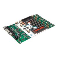
All connections are shown in Figure 3-19.
Figure 3-19. Connection for Serial High-voltage Programming
 Loading...