Hardware Description
AVR STK500 User Guide 3-23
1925C–AVR–3/03
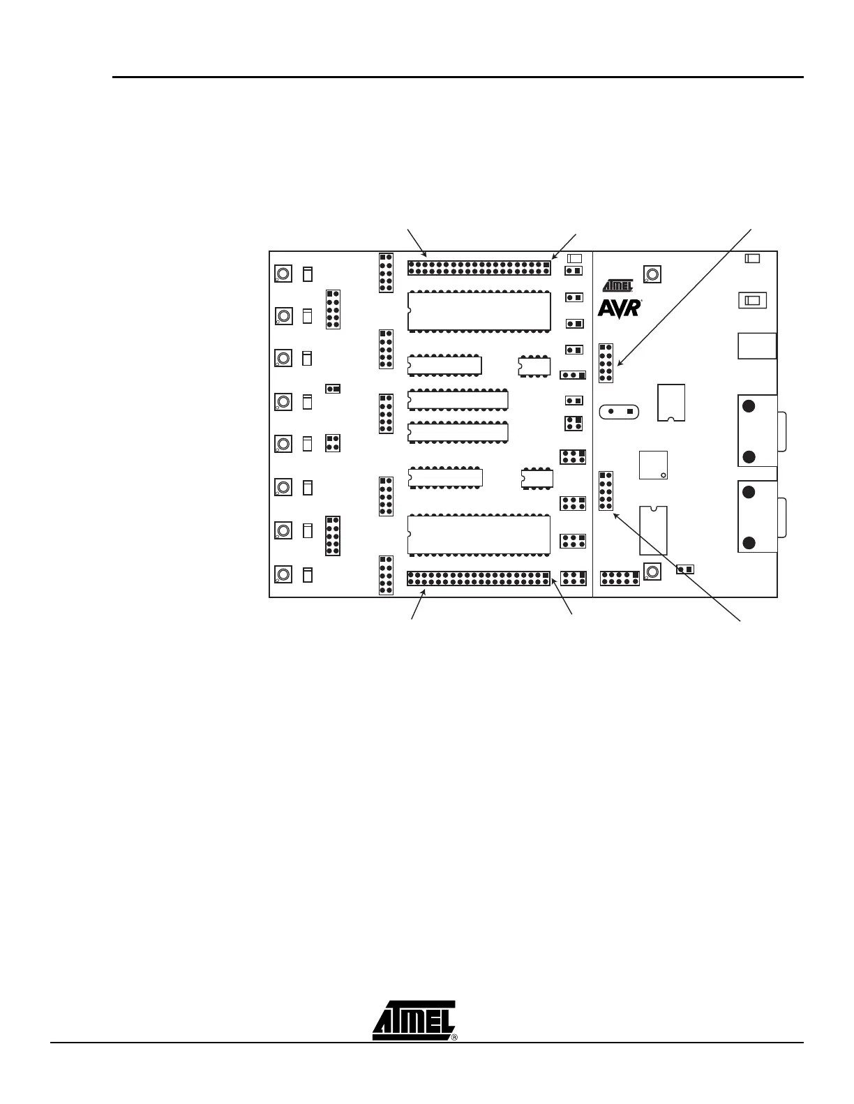
3.9 Expansion
Connectors
STK500 has two expansion connectors, one on each side of the programming module.
All AVR I/O ports, programming signals and control signals are routed to the expansion
connectors. The expansion connectors allow easy prototyping of applications
with STK500. The pinout of the expansion connectors is shown in Figure 3-34 and Fig-
ure 3-35.
Figure 3-33. Expansion Headers
Expansion Header 0
Expansion Header 1
Prog Ctrl
Prog Data
Pin 1
Pin 1
 Loading...