Hardware Description
AVR STK500 User Guide 3-5
1925C–AVR–3/03
3.5 Description of
User RS-232
Interface
The STK500 includes two RS-232 ports. One RS-232 port is used for communicating
with AVR Studio. The other RS-232 can be used for communicating between the target
AVR microcontroller in the socket and a PC serial port connected to the RS-232. To use
the RS-232, the UART pins of the AVR need to be physically connected to the RS-232.
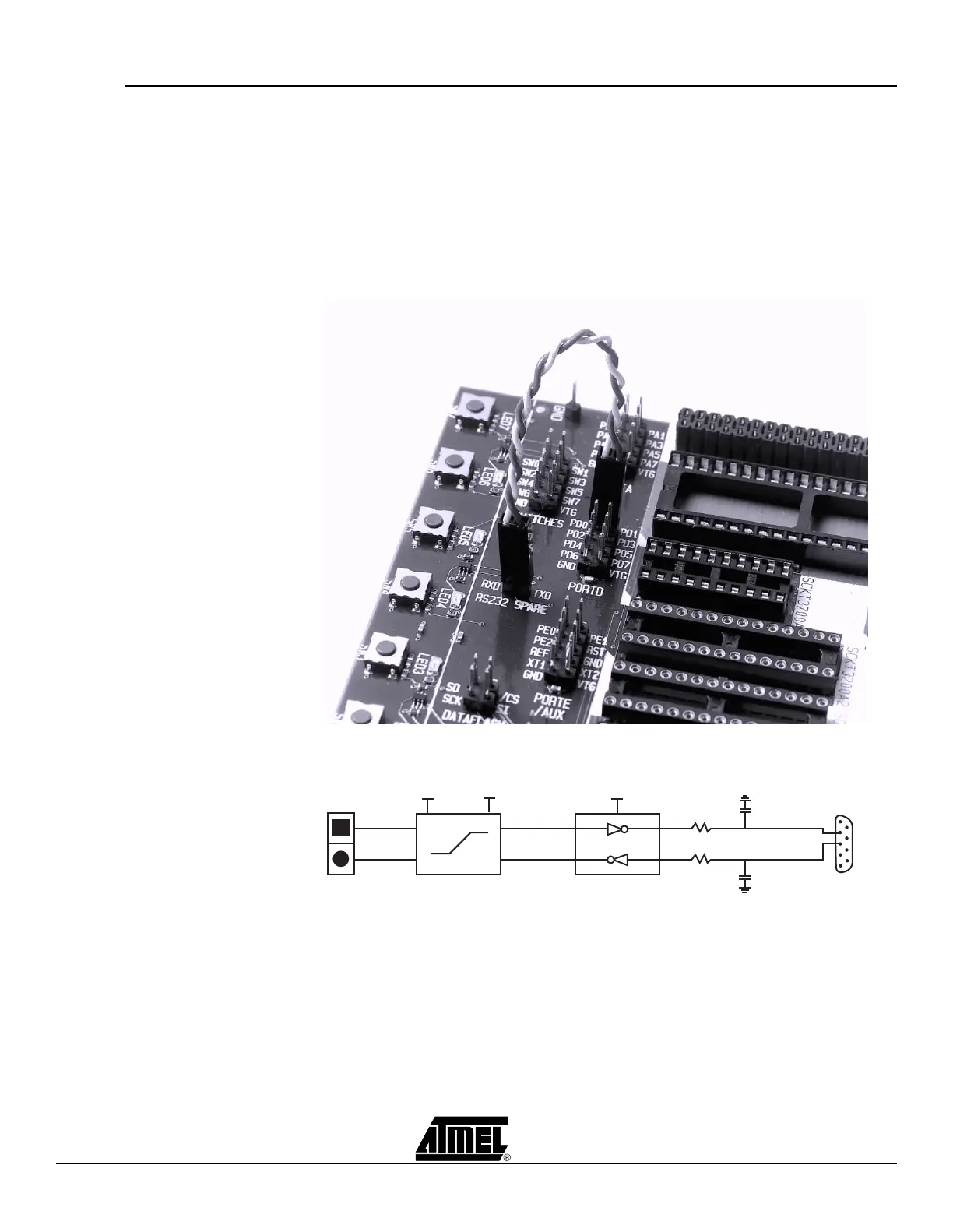
The 2-pin header marked “RS232 SPARE” can be used for connecting the RS-232 con-
verter to the UART pins on the target AVR microcontroller in the socket. Use the 2-wire
cable to connect the UART pins to the RS-232. The connection is shown in Figure 3-9.
The block schematic of the RS-232 connection is shown in Figure 3-10.
Figure 3-9. Connection of I/O Pins to UART
Figure 3-10. Schematic of UART Pin Connections
TXD
RXD
Voltage
Converter
VTG 5V
MAX202CSE
470R
470R
1n2
1n2
2
3
5V
RS-232
 Loading...