Hardware Description
AVR STK500 User Guide 3-3
1925C–AVR–3/03
3.3 Connection of
LEDs and
Switches
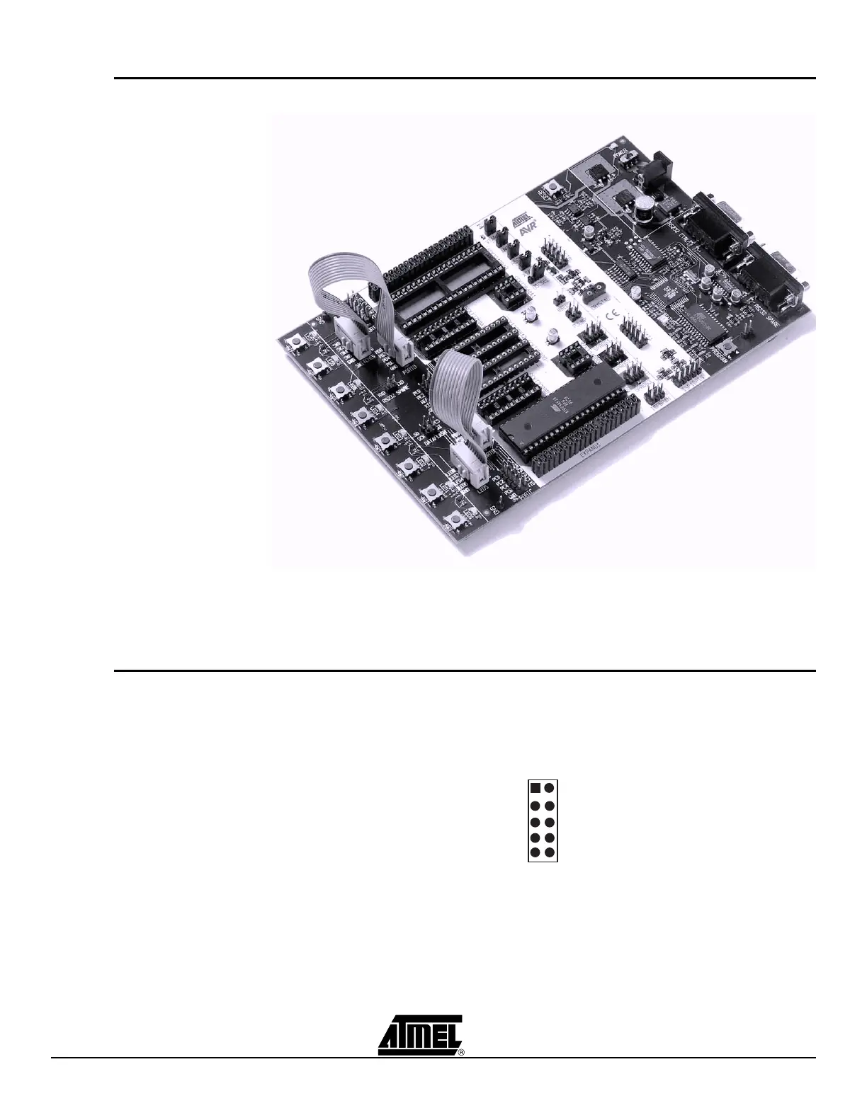
Figure 3-4. Connection of LEDs and Switches to I/O Port Headers
Any I/O port of the AVR can be connected to the LEDs and switches using the 10-wire
cables. The headers are supplied with VTG (target V
CC
) and GND lines in addition to the
signal lines.
3.4 Port Connectors The pinout for the I/O port headers is explained in Figure 3-5. The square marking indi-
cates pin 1.
Figure 3-5. General Pinout of I/O Port Headers
The PORTE/AUX header has some special signals and functions in addition to the
PORTE pins. The pinout of this header is shown in Figure 3-6.
Px1
Px3
Px5
Px7
VTG
Px0
Px2
Px4
Px6
GND
1 2
PORTx
 Loading...