Hardware Description
3-8 AVR STK500 User Guide
1925C–AVR–3/03
3.7 Target Socket
Section
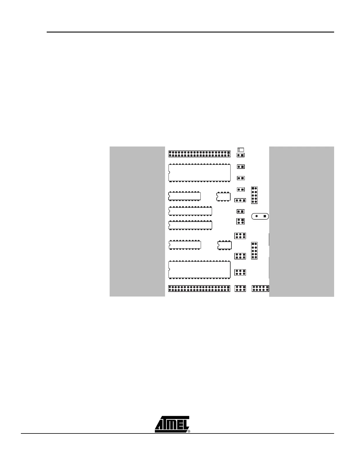
The programming module consists of the eight sockets in the white area in the middle of
the starter kit. In these sockets, the target AVR devices can be inserted for programming
and are used in the application.
Note: Only one AVR device should be inserted in the sockets at a time.
The AVR Flash memory is guaranteed to be correct after 1,000 programming opera-
tions; the typical lifetime of the Flash memory is much longer.
Note: When inserting a device in the socket, notice the orientation of the device.
The notch on the short side of the part must match the notch on the socket. If the device
is inserted the wrong way, it may damage the part and the starter kit.
The socket section is used for both running applications and target device programming.
Figure 3-15. The STK500 Programming Module
The part inserted in the socket can be programmed in the system from AVR Studio with
two different methods:
1. AVR In-System Programming (ISP) running at the parts normal supply voltage.
2. High-voltage Programming, where the supply voltage is always 5 volts.
Four general nets (VTARGET, RESET, XTAL1 and AREF) can be connected to the
socket section.
The following sections describe how to use both programming methods. For instructions
on using the AVR Studio programming software, see Section 5, “Using AVR Studio” on
page 5-1.
 Loading...