Hardware Description
3-10 AVR STK500 User Guide
1925C–AVR–3/03
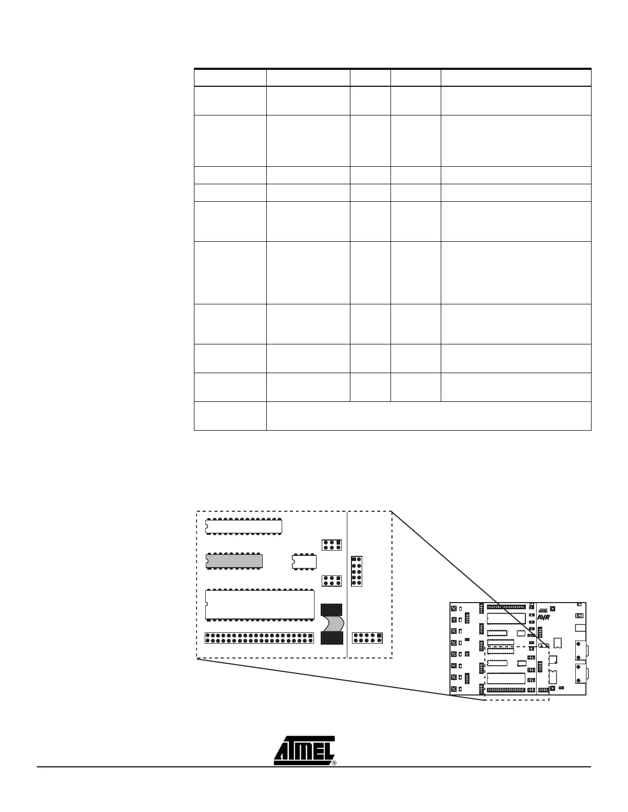
Figure 3-16 shows an example of how AT90S2313 can be In-System Programmed. The
6-wire cable is connected from the ISP6PIN header to the red SPROG3 target ISP
header, and the AT90S2313 part is inserted in the red socket marked “SCKT3100D3”.
Figure 3-16. Example Connection for Programming AT90S2313
Table 3-2. AVR Sockets
AVR Devices STK500 Socket Color Number Target ISP Header
AT90S1200
AT90S2313
SCKT3300D3 Red 3 SPROG3
AT90S2323
AT90S2343
AT t i ny 12
AT t i ny 22
SCKT3400D1 Blue 1 SPROG1. Connect RST on
PORTE to PB5 on PORTB.
Connect XTI on PORTE to PB3
(XTAL1 on 2323) on PORTB.
ATtiny11 SCKT3400D1 Blue 1 High-voltage Programming only
ATtiny28 SCKT3500D- None – High-voltage Programming only
AT90S4414
AT90S8515
ATmega161
SCKT3000D3 Red 3 SPROG3
AT90S4434
AT90S8535
ATmega16
ATmega163
ATmega323
SCKT3100A3 Red 3 SPROG3
AT90S2333
AT90S4433
AT m e ga 8
SCKT3200A2 Green 2 SPROG2
ATtiny15 SCKT3600A1 Blue 1 SPROG1. Connect RST on
PORTE to PB5 on PORTB.
N/A SCKT3700A1 Blue 1 Socket is not in use in this version
of STK500
ATmega103
ATmega128
Use the STK501 Top Module
AVR
SCKT3300D3
SPROG1
SPROG2
SPROG3
ISP6PIN
 Loading...