Hardware Description
AVR STK500 User Guide 3-19
1925C–AVR–3/03
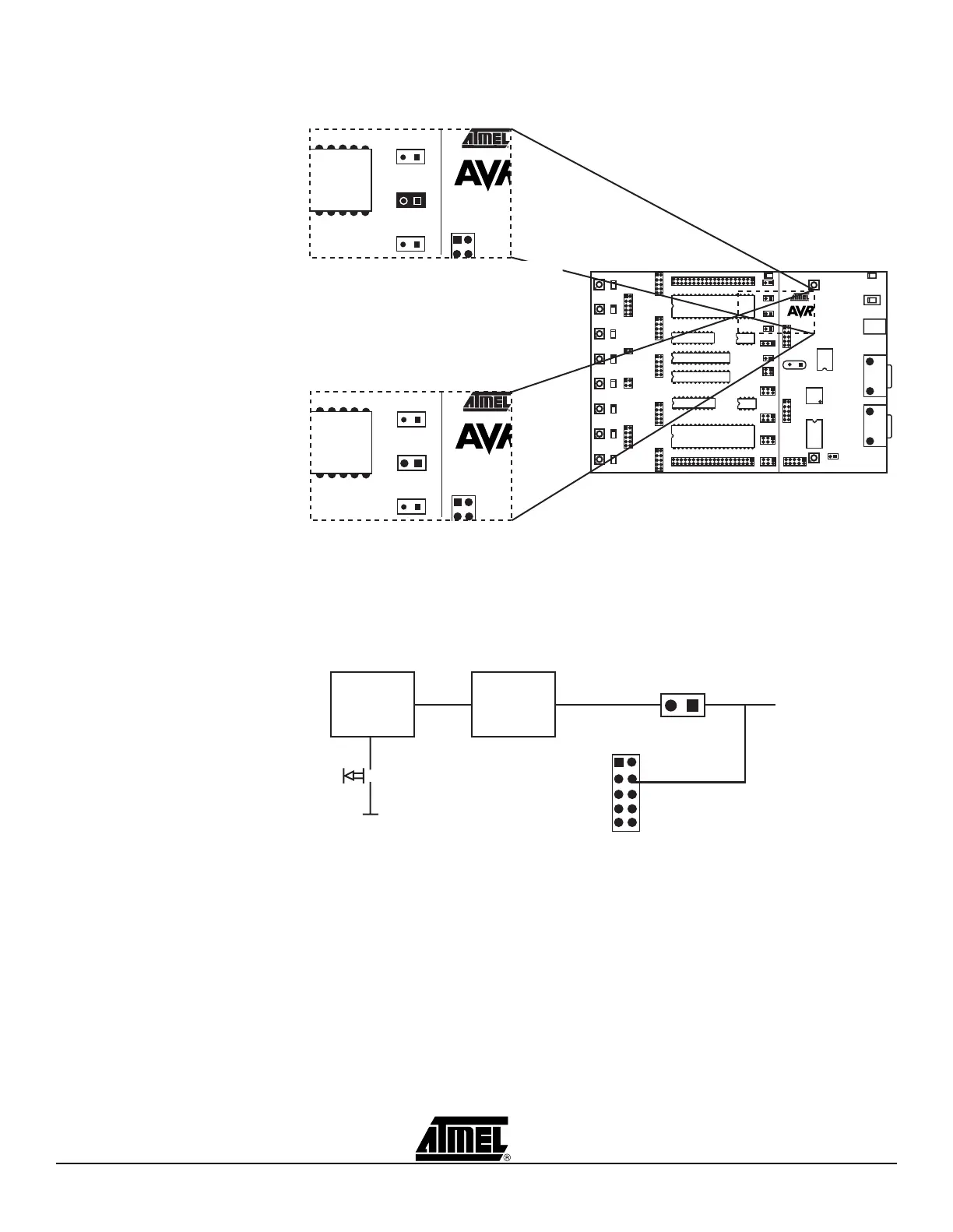
Figure 3-25. RESET Jumper Options
The STK500 master microcontroller controls the RESET signal to the target AVR. The
RESET signal is accessible on the PORTE/AUX header; this pin can also be used for
external RESET signal. Figure 3-26 shows the internal connection of the RESET signal.
Figure 3-26. Internal RESET Connection
Note: During High-voltage Programming, STK500 applies 12V to the AVR’s RESET
line. Thus, an external reset circuit not capable of handling this must be discon-
nected before High-voltage Programming the AVR.
AREF
RESET
XTAL1
Jumper Mounted
AREF
RESET
XTAL1
Jumper not Mounted
On-board RESET Signal Disconnected
On-board RESET Signal Connected (default)
PE1
RST
GND
XT2
VTG
PE0
PE2
REF
XT1
GND
1 2
Master
MCU
RESET NET
0V - VTG - 12V
RESET
CIRCUIT
RESET
PORTE/AUX
RESET
Jumper
 Loading...