113
8271D–AVR–05/11
ATmega48A/PA/88A/PA/168A/PA/328/P
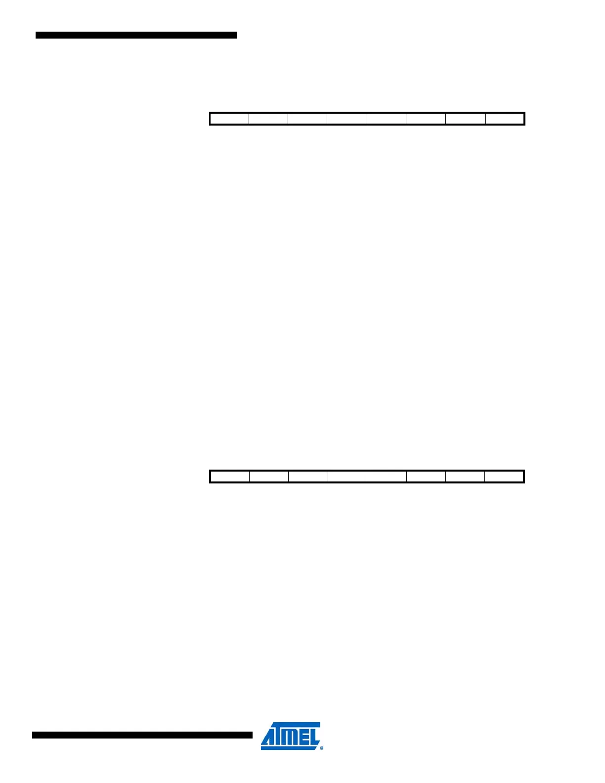
15.9.6 TIMSK0 – Timer/Counter Interrupt Mask Register
• Bits 7:3 – Reserved
These bits are reserved bits in the ATmega48A/PA/88A/PA/168A/PA/328/P and will always read
as zero.
• Bit 2 – OCIE0B: Timer/Counter Output Compare Match B Interrupt Enable
When the OCIE0B bit is written to one, and the I-bit in the Status Register is set, the
Timer/Counter Compare Match B interrupt is enabled. The corresponding interrupt is executed if
a Compare Match in Timer/Counter occurs, i.e., when the OCF0B bit is set in the Timer/Counter
Interrupt Flag Register – TIFR0.
• Bit 1 – OCIE0A: Timer/Counter0 Output Compare Match A Interrupt Enable
When the OCIE0A bit is written to one, and the I-bit in the Status Register is set, the
Timer/Counter0 Compare Match A interrupt is enabled. The corresponding interrupt is executed
if a Compare Match in Timer/Counter0 occurs, i.e., when the OCF0A bit is set in the
Timer/Counter 0 Interrupt Flag Register – TIFR0.
• Bit 0 – TOIE0: Timer/Counter0 Overflow Interrupt Enable
When the TOIE0 bit is written to one, and the I-bit in the Status Register is set, the
Timer/Counter0 Overflow interrupt is enabled. The corresponding interrupt is executed if an
overflow in Timer/Counter0 occurs, i.e., when the TOV0 bit is set in the Timer/Counter 0 Inter-
rupt Flag Register – TIFR0.
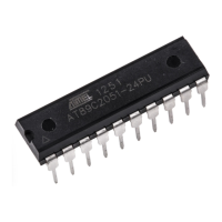
15.9.7 TIFR0 – Timer/Counter 0 Interrupt Flag Register
• Bits 7:3 – Reserved
These bits are reserved bits in the ATmega48A/PA/88A/PA/168A/PA/328/P and will always read
as zero.
• Bit 2 – OCF0B: Timer/Counter 0 Output Compare B Match Flag
The OCF0B bit is set when a Compare Match occurs between the Timer/Counter and the data in
OCR0B – Output Compare Register0 B. OCF0B is cleared by hardware when executing the cor-
responding interrupt handling vector. Alternatively, OCF0B is cleared by writing a logic one to
the flag. When the I-bit in SREG, OCIE0B (Timer/Counter Compare B Match Interrupt Enable),
and OCF0B are set, the Timer/Counter Compare Match Interrupt is executed.
• Bit 1 – OCF0A: Timer/Counter 0 Output Compare A Match Flag
The OCF0A bit is set when a Compare Match occurs between the Timer/Counter0 and the data
in OCR0A – Output Compare Register0. OCF0A is cleared by hardware when executing the cor-
responding interrupt handling vector. Alternatively, OCF0A is cleared by writing a logic one to
Bit 7 6 5 4 3 2 1 0
(0x6E) – – – – – OCIE0B OCIE0A TOIE0 TIMSK0
Read/Write RRRRRR/WR/WR/W
Initial Value 0 0 0 0 0 0 0 0
Bit 76543210
0x15 (0x35) – – – – – OCF0B OCF0A TOV0 TIFR0
Read/Write R R R R R R/W R/W R/W
Initial Value 0 0 0 0 0 0 0 0