33
8271D–AVR–05/11
ATmega48A/PA/88A/PA/168A/PA/328/P
9.5 Low Frequency Crystal Oscillator
The Low-frequency Crystal Oscillator is optimized for use with a 32.768kHz watch crystal. When
selecting crystals, load capacitance and crystal’s Equivalent Series Resistance, ESR must be
taken into consideration. Both values are specified by the crystal vendor.
ATmega48A/PA/88A/PA/168A/PA/328/P oscillator is optimized for very low power consumption,
and thus when selecting crystals, see Table for maximum ESR recommendations on 6.5pF,
9.0pF and 12.5pF crystals
Note: 1. Maximum ESR is typical value based on characterization
The Low-frequency Crystal Oscillator provides an internal load capacitance, see Table 9-8 at
each TOSC pin.
The capacitance (Ce+Ci) needed at each TOSC pin can be calculated by using:
where:
– Ce - is optional external capacitors as described in Figure 9-2 on page 30
– Ci - is the pin capacitance in Table 9-8
– CL - is the load capacitance for a 32.768kHz crystal specified by the crystal vendor
– CS - is the total stray capacitance for one TOSC pin.
Crystals specifying load capacitance (CL) higher than 6 pF, require external capacitors applied
as described in Figure 9-2 on page 30.
The Low-frequency Crystal Oscillator must be selected by setting the CKSEL Fuses to “0110” or
“0111”, as shown in Table 9-10 on page 34. Start-up times are determined by the SUT Fuses as
shown in Table 9-9.
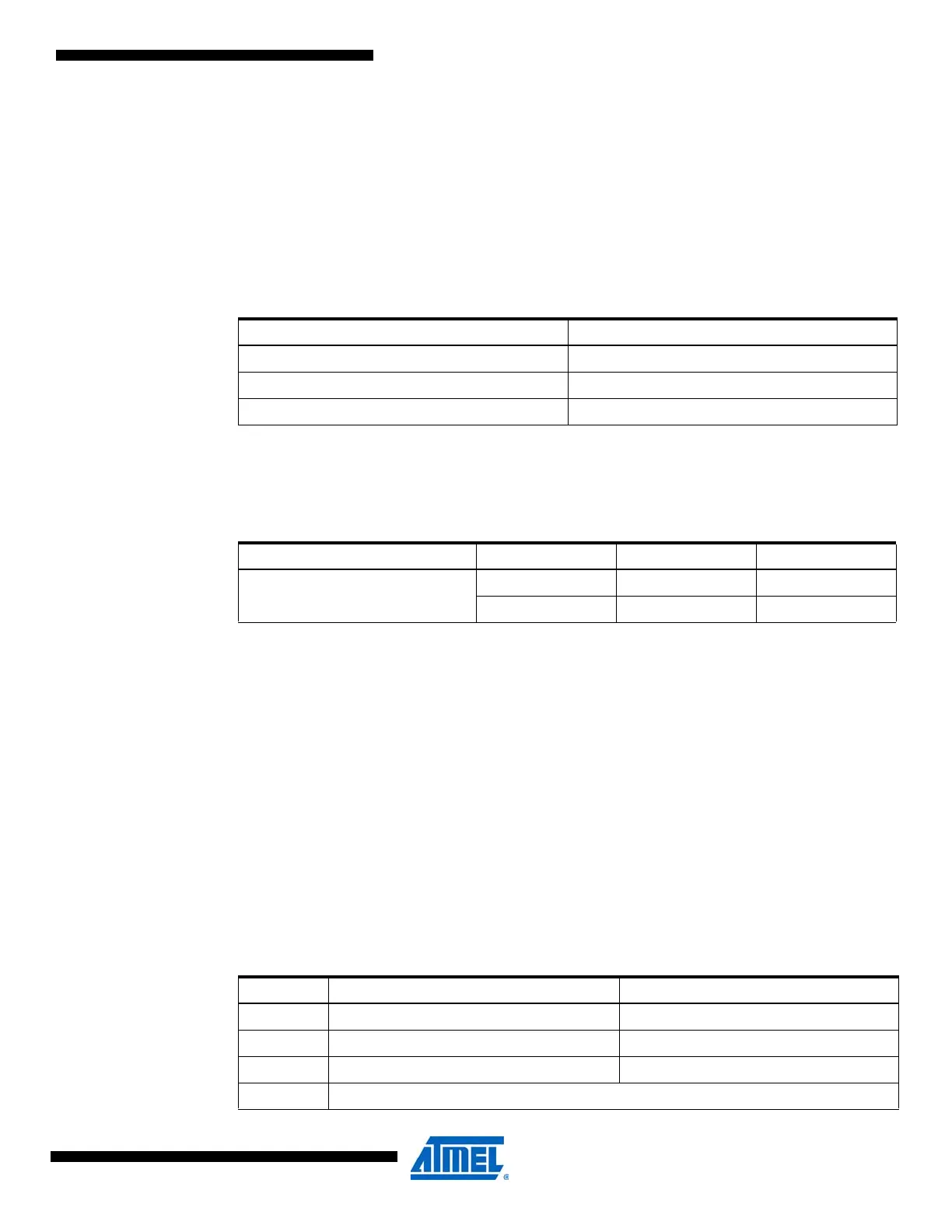
Table 9-7. Maximum ESR Recommendation for 32.768kHz Crystal
Crystal CL (pF) Max ESR [kΩ]
(1)
6.5 75
9.0 65
12.5 30
Table 9-8. Capacitance for Low-frequency Oscillator
Device 32kHz Osc. Type Cap(Xtal1/Tosc1) Cap(Xtal2/Tosc2)
ATmega48A/PA/88A/PA/168A/PA/3
28/P
System Osc. 18pF 8pF
Timer Osc. 18pF 8pF
Table 9-9. Start-up Times for the Low-frequency Crystal Oscillator Clock Selection
SUT1...0 Additional Delay from Reset (V
CC
= 5.0V) Recommended Usage
00 4 CK Fast rising power or BOD enabled
01 4 CK + 4.1ms Slowly rising power
10 4 CK + 65ms Stable frequency at start-up
11 Reserved