64
8271D–AVR–05/11
ATmega48A/PA/88A/PA/168A/PA/328/P
0xC1B out SPH,r16 ; Set Stack Pointer to top of RAM
0xC1C ldi r16,low(RAMEND)
0xC1D out SPL,r16
0xC1E sei ; Enable interrupts
0xC1F <instr> xxx
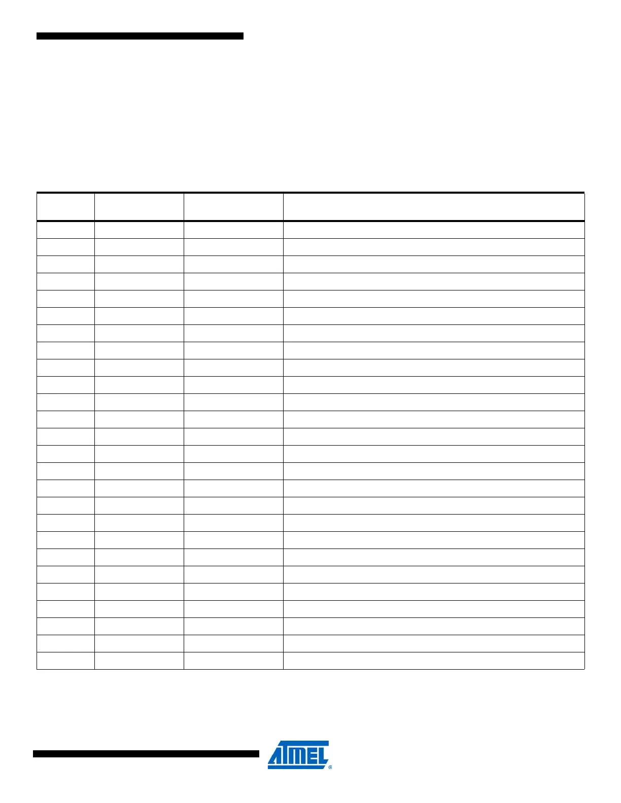
12.3 Interrupt Vectors in ATmega168A and ATmega168PA
Notes: 1. When the BOOTRST Fuse is programmed, the device will jump to the Boot Loader address at reset, see ”Boot Loader Sup-
port – Read-While-Write Self-Programming” on page 280.
2. When the IVSEL bit in MCUCR is set, Interrupt Vectors will be moved to the start of the Boot Flash Section. The address of
each Interrupt Vector will then be the address in this table added to the start address of the Boot Flash Section.
Table 12-4. Reset and Interrupt Vectors in ATmega168A and ATmega168PA
VectorNo.
Program
Address
(2)
Source Interrupt Definition
1 0x0000
(1)
RESET
External Pin, Power-on Reset, Brown-out Reset and Watchdog System Reset
2 0x0002 INT0 External Interrupt Request 0
3 0x0004 INT1 External Interrupt Request 1
4 0x0006 PCINT0 Pin Change Interrupt Request 0
5 0x0008 PCINT1 Pin Change Interrupt Request 1
6 0x000A PCINT2 Pin Change Interrupt Request 2
7 0x000C WDT Watchdog Time-out Interrupt
8 0x000E TIMER2 COMPA Timer/Counter2 Compare Match A
9 0x0010 TIMER2 COMPB Timer/Counter2 Compare Match B
10 0x0012 TIMER2 OVF Timer/Counter2 Overflow
11 0x0014 TIMER1 CAPT Timer/Counter1 Capture Event
12 0x0016 TIMER1 COMPA Timer/Counter1 Compare Match A
13 0x0018 TIMER1 COMPB Timer/Coutner1 Compare Match B
14 0x001A TIMER1 OVF Timer/Counter1 Overflow
15 0x001C TIMER0 COMPA Timer/Counter0 Compare Match A
16 0x001E TIMER0 COMPB Timer/Counter0 Compare Match B
17 0x0020 TIMER0 OVF Timer/Counter0 Overflow
18 0x0022 SPI, STC SPI Serial Transfer Complete
19 0x0024 USART, RX USART Rx Complete
20 0x0026 USART, UDRE USART, Data Register Empty
21 0x0028 USART, TX USART, Tx Complete
22 0x002A ADC ADC Conversion Complete
23 0x002C EE READY EEPROM Ready
24 0x002E ANALOG COMP Analog Comparator
25 0x0030 TWI 2-wire Serial Interface
26 0x0032 SPM READY Store Program Memory Ready