3. Remove the terminal cover. Isolate element wires from the terminal block and check
resistance with an ohmmeter. If there is resistance, no further action is needed. If
there is not any resistance, replacement is needed. Disconnect and mark the terminal
block for reassembly. It is important to straighten or cut o the loops at the end of the
element leads in order to prevent damage to the insulation cylinder when the leads are
pulled through it.
4. Mark the shell and end anges for easy assembly alignment. Remove the end ange
closest to the burned-out element. Carefully remove the end ange and end disk.
5. Carefully feed the element lead wires through the shell while removing the defective
element from its seat. Be careful not to damage the insulation.
6. If necessary, straighten the new wire leads. Align the wires with the wire paths in the
insulation and feed the wires through the shell by inserting a guide tube into the wire
path and pushing the wire through the guide tube, or by putting a string through the
hole, tying it to the wire, and pulling it through the wire path.
7. Place the wires to maintain the maximum distance between them. Carefully position the
element in place. Align any ports if applicable.
8. After installing the new element, insert the thermocouple to ensure alignment.
9. Install the insulation end disk. Align
the end ange with the shell and install
it. If necessary, a bar clamp can be
used to gently compress the assembly
enough to align the screw holes.
10. Ensure that the leads do not short-
circuit against the outside case.
11. Use a ohmmeter to check for short
circuits. Install the terminal block and
attach the wires. Cut o any excess
wires. Check again for short circuits
and correct any problems before
completing the installation.
12. Inspect the embedding material for
cracks or damage. If the embedding
must be repaired, refer to the
Embedding & Patching Elements
(Section G.2, p. 13)
Series 31XX, 32XX Furnaces | G. Furnace and Element Maintenance 17
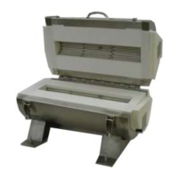
Figure G.4 - Safe Distance Between Lead Wires