16 Series 31XX, 32XX Furnaces | G. Furnace and Element Maintenance
8. After installing the new element, insert the thermocouple to ensure alignment.
9. Install the insulation end disk. Align the end ange with the shell and install it. If
necessary, a bar clamp can be used to gently compress the assembly enough to align
the screw holes.
10. Ensure that the leads do not short circuit against the outside case.
11. Use an ohmmeter to check for short circuits. Install the terminal block and attach
the wires. Cut o any excess wires. Check again for short circuits, and correct any
problems before completing the installation.
12. Inspect the embedding material for cracks or damage. If the embedding must be
repaired, refer to the Embedding & Patching Elements section of this manual (Section
G.2, p. 13).
13. If applicable, mount the furnace on the testing machine. Connect the leads and
instrumentation, and install the terminal covers.
14. If any insulation has been replaced, follow the bake-out procedures outlined in the
furnace manual. Bake-out is not necessary unless the insulation has been replaced.
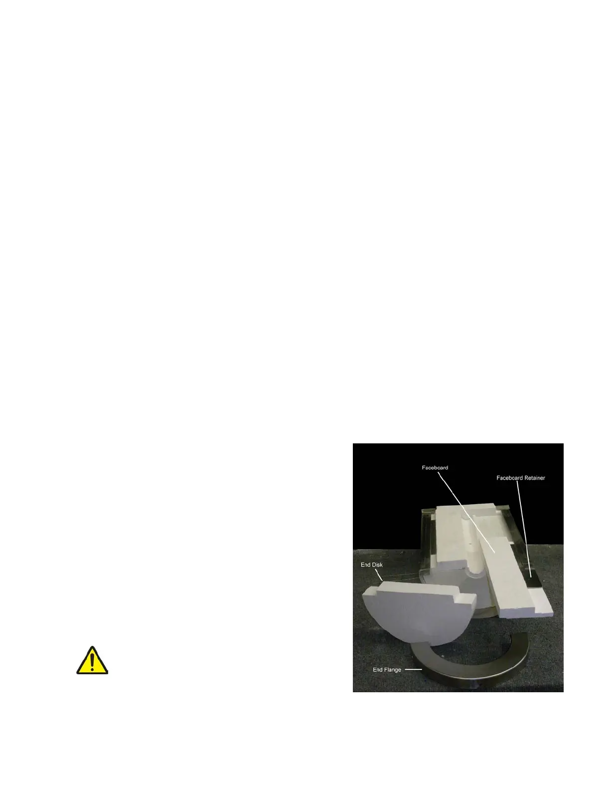
3210 Split Tube Furnace Element Replacement
The element replacement procedure described
in this section is for ATS Series 3210 Split Tube
Furnace types only. Refer to Figure G.3 for an
identication of parts.
1. Turn o furnace and allow to cool completely.
2. Disconnect the power and instrumentation
wiring from the furnace. If applicable, remove
the furnace from the testing machine and
position the furnace on the workbench in a
suitable cradle.
WARNING: Failure to completely
disconnect the furnace from the
power supply before attempting
disassembly may cause
personal injury or death.
Figure G.3 - Series 3210 Furnace