34
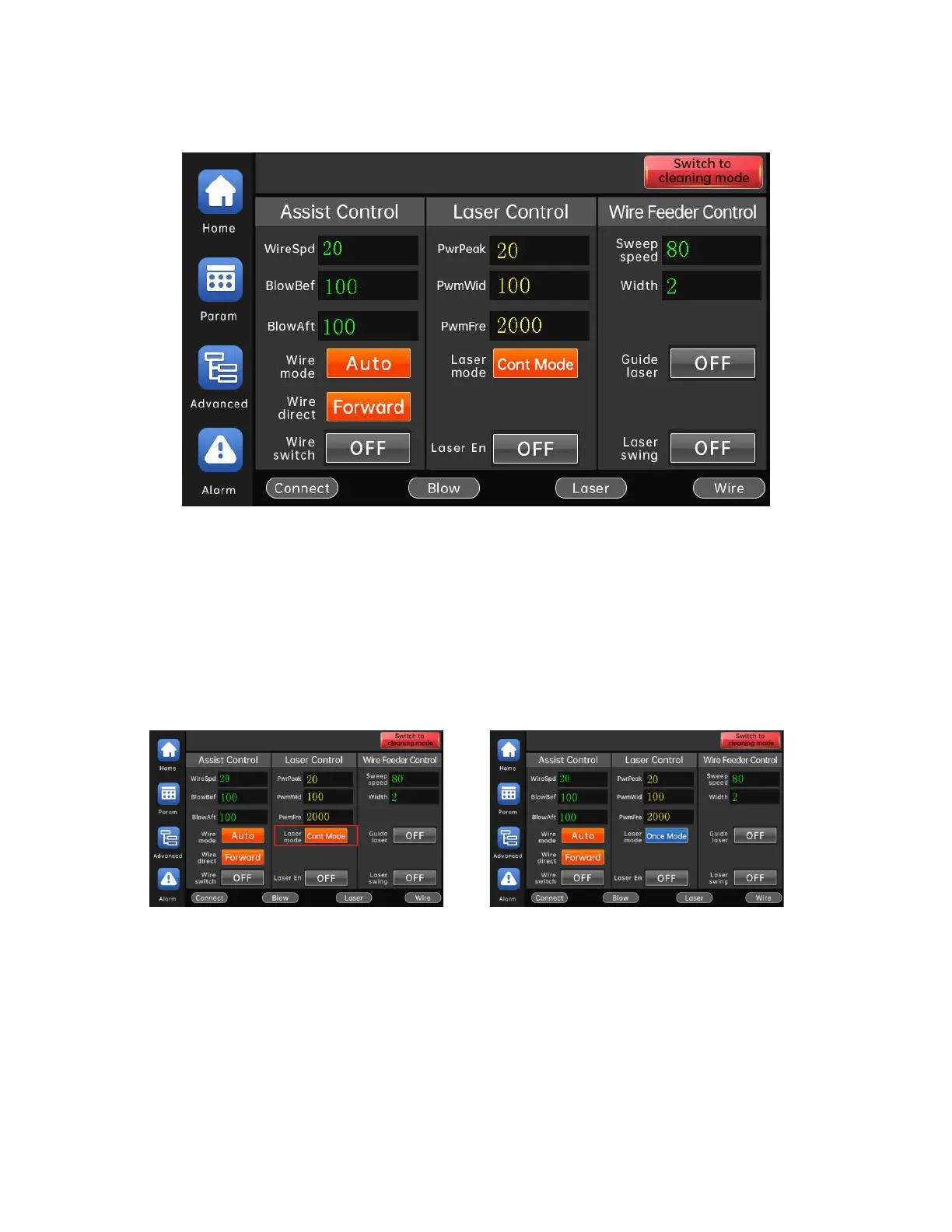
After the system is powered on, it will enter the welding work interface by default, as
shown in the figure below:
The welding work interface is the most commonly used interface for users. Under
this interface, users can set parameters, turn on/off enable control, switch working modes,
and light emitting methods.
Output power of the welding head = laser power x peak power x PWM duty cycle
Click the "LaserMd" button to switch the light emitting mode.
Continuous light: After turning on the laser enable, when the light-emitting
conditions are met, the light can be continuously emitted by pressing the light-emitting
switch of the welding head, and the light can be turned off by releasing the light-emitting
switch.
Point shot light: When the light is spotted, after the laser enable is turned on, the