Getting Started Guide
38 APx511 B Series Hearing Instrument Analyzer: Getting Started Guide
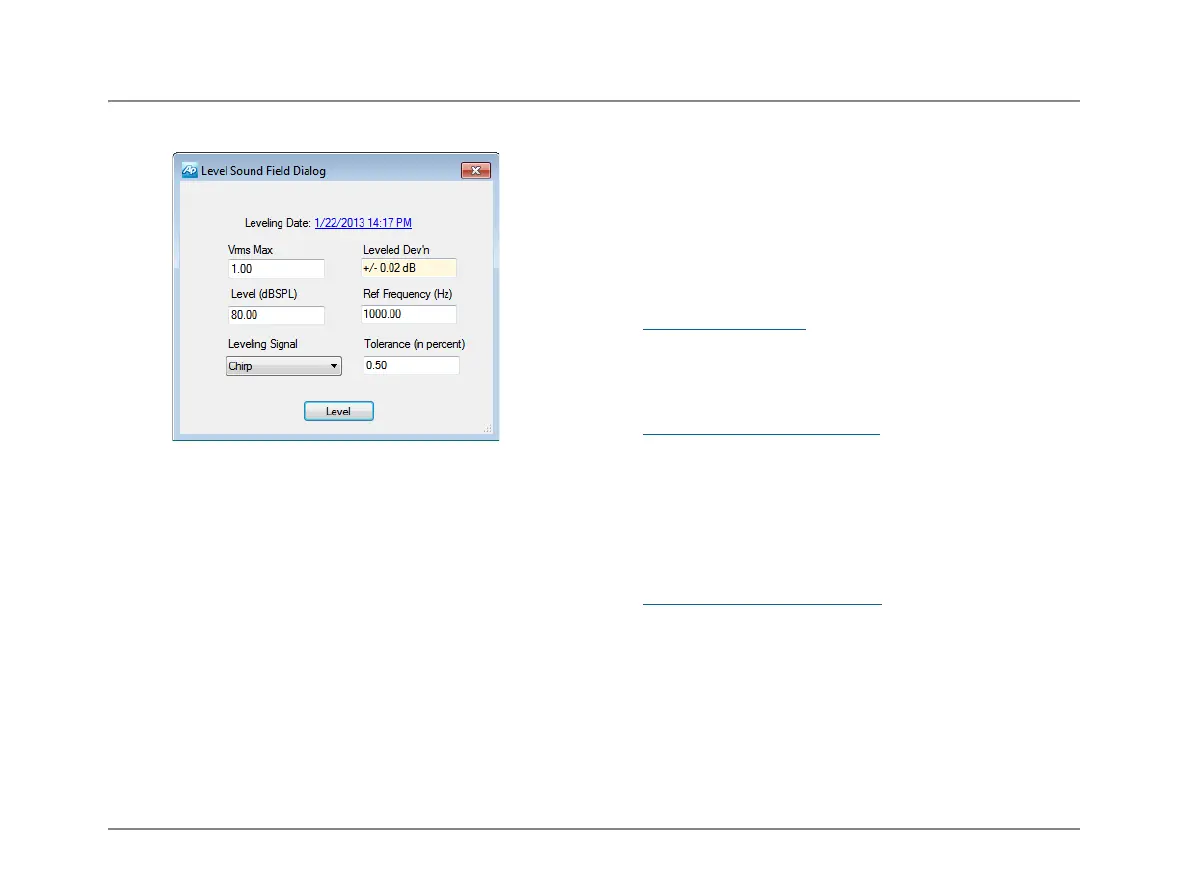
Leveling the test chamber
This tool will set chamber acoustic output to a calibrated
level, and equalize the analyzer output to compensate for
loudspeaker response.
If no leveling data is on file for this system, the Leveling
Date field will read “No Leveling Data.”
Leveling uses the regulation function in APx.
Put the microphone on the chamber test point spot. Fit the
dummy mic to the coupler to maintain a constant acoustic
space. Close and seal the chamber.
Click Level. The program finds the generator level required
to achieve the target level and sweeps the chamber at that
level. A compensation curve is created and applied to the
generator output. The chamber is swept again with leveling
compensation, and the maximum deviation from flat
response at the reference frequency is shown in the Leveled
Deviation field.
Preparing the DUT
For testing purposes, hearing instruments are considered to
be one of two types: “behind the ear” (BTE), which uses a
short acoustic tube to route the instrument output to the ear
canal, and “in the ear” (ITE) which outputs sound directly
into the ear canal.
Fit the appropriate microphone coupler to the acoustic out-
put of your device under test (DUT). Fit the measurement
microphone into the coupler.
Powering the DUT
For testing purposes, the internal battery is replaced with a
battery simulator (or pill). Fit the battery simulator into the
DUT and connect it to the battery adapter jack within the
chamber.
Testing the Acoustic input
The hearing instrument is typically tested in an acoustic
chamber, where a loudspeaker stimulates the instrument’s
receiver (internal microphone). Set the DUT in the cham-
ber’s optimal acoustic test point (the “sweet spot”), and
attach the microphone coupler and measurement micro-
phone.
Set the DUT’s program switch to acoustic mode.
Testing the Magnetic input
The acoustic chamber is also fitted with a telephone mag-
netic field simulator (TMFS, or telecoil) to induce a signal
into the DUT’s telecoil input. The optimal placement of the
DUT for magnetic coupling must be discovered by trial, as
described in the procedure below.
For telecoil testing, set the DUT’s program switch to tele-
coil mode.
 Loading...