Do you have a question about the Audiovox Prestige APS-25CH and is the answer not in the manual?
Turn ignition on, press valet switch 3 times, then turn ignition off/on.
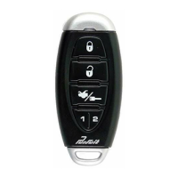
Press transmitter Lock button to change feature or press valet switch.
Press transmitter Lock button to change feature or press valet switch.
Press transmitter Lock button to change feature or press valet switch.
Press transmitter Lock button to change feature or press valet switch.
Press transmitter Lock button to change feature or press valet switch.
Turn ignition key off to exit program mode.
Provides an additional hardwire remote output for optional upgrades.
Mount inside passenger compartment, avoid engine compartment and factory electronics.
Mount in engine compartment, protected, downward facing, secure with bracket.
Mount to grounded metal surface, avoid water, ensure plunger depression.
Install in dash for visual indicator, ensure wire routing access.
Mount on solid surface, ensure sensitivity adjustment is accessible.
Select accessible location, conceal for security, drill 1/4" hole, check clearance.
+12 VDC pulsed output to flash vehicle's parking lights.
Controls voltage sensing circuit, sensitive to interior lights or fans.
For hardwiring pin switches, disable voltage sense, connect to +12V constant.
300 mA pulsed output, use for external relay coils, avoid high current.
Positive output to siren, route through grommet, connect to siren positive.
Connect to solid metal part of vehicle's chassis.
+12 VDC when ignition is ON and CRANK, off when OFF.
Instant on ground trigger, connect to hood and trunk pin switches.
Connect to negative output of door courtesy light switch.
Connect to positive output of door courtesy light switch.
For starter cut relay, connect to terminal 86 of relay.
Grey & Black 2 Pin connector for valet switch.
Red & Blue wires on white connector for LED.
Red & Green wires on white connector for door lock control.
Red wire for lock pulse, green wire for unlock pulse to factory switch.
Red wire for unlock pulse, green wire for lock pulse to factory switch.
Refer to wiring supplement for resistive, 4 wire polarity reversal, 5 wire alternating circuits.
Learn interior light delay by transmitter sequence to avoid chirp.
Extend and cable tie antenna wire, avoid high current wire looms.
Adjust sensitivity by turning screw, test with fist strike to rear bumper.
Wrap wires in tubing or tape, secure with ties, protect from sharp surfaces.
Check operation, explain to customer, place tags on switches.