5251
The Universal Sound
Owner’s manual
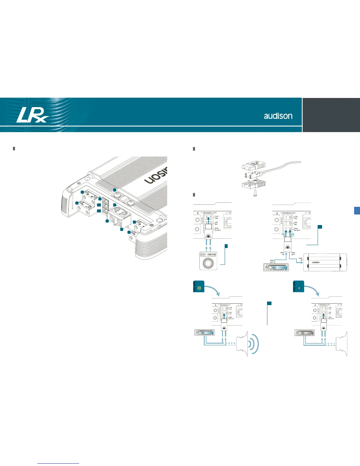
Power Supply and output terminal description
1_ Protection fuse: 40 A (LRx 4.5) / 100 A (LRx 4.1k);
2_ Anti-short circuit protective shield;
3_ - Power (Ground): terminal block for the
amplifier power supply negative pole
connection. Insert the battery
negative cable or a wire
connected to the vehicle
chassis here. The hole
accepts cables up to
2 A.W.G. For the best
current transfer,
we recommend the use
of cables with as big a
section as possible or,
at least, with the same section
as the wire connected to the positive pole;
4_ + Power (11÷15 VDC): terminal block for
the amplifier power supply positive pole connection.
Insert the battery positive cable here. The hole accepts cables
up to 2 A.W.G. For the best current transfer, we recommend the
use of cables with as big a section as possible or, at least, with the
same section as the wire connected to the negative pole;
5_ + Left A/B Speaker Out: + Left speaker terminal of A/B channels;
6_ - Left A/B Speaker Out: - Left speaker terminal of A/B channels;
7_ + Right A/B Speaker Out: + Right speaker terminal of A/B channels;
8_ - Right A/B Speaker Out: - Right speaker terminal of A/B channels;
9_ Remote Sub Volume: Inputs for sub volume remote control, optional VCRA;
10_ Speaker ON: Inputs for turning on the amplifier through the speaker cable.
If source does not have a 12 VDC Remote output, connect any power output, even
in parallel with a factory speaker here for turning on the amplifier;
11_ Remote IN/OUT: REM IN, terminal for the Remote cable coming from the device which
turns on the amplifier. Voltage must be between 7 and 16 VDC. REM OUT, terminal for
repeating Remote voltage and turning on other electronic devices. Output voltage is
12 VDC at 50 mA. Connection made to the SPK ON, also without the REM IN, will supply
voltage to the REM OUT to turn on other devices.