12
33
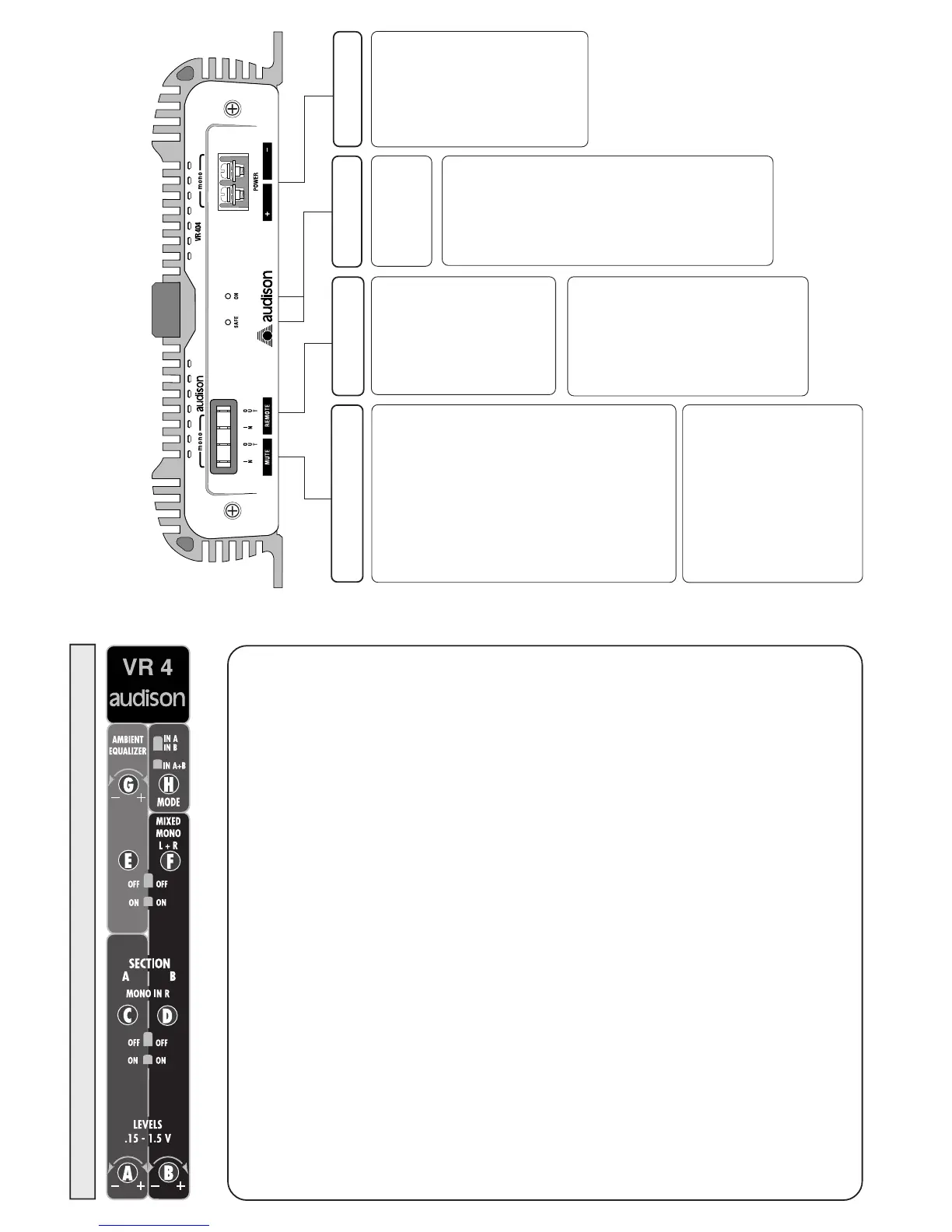
VR 404
SECTION "A" (A-C)
Linker (Left) und Rechter (Right) Kanal der A Sektion
A• LEVELS: Empfindlichkeitsregler Links und Rechts von Kanäle A. Die Empfindlichkeit
wechselt von 0,15 bis 1,5 V.
C• MONO IN R: Selektiert die Linken und Rechten Ausgänge in stereo (OFF) oder mono
(ON). Bitte den Rechten Mono Eingang IN A - IN B oder IN B für BRIDGE
verwenden.
SECTION "B" (B-D-F)
Linker (Left) und Rechter (Right) Kanal der B Sektion
B• LEVELS: Empfindlichkeitsregler Links und Rechts von Kanäle B. Die Empfindlichkeit
wechselt von 0,15 bis 1,5 V.
D. MONO IN R: Selektiert die Linken und Rechten Ausgänge in stereo (OFF) oder mono
(ON). Bitte den Rechten Mono Eingang IN A - IN B oder IN B für BRIDGE
verwenden.
F• MIXED MONO (L+R): Auf der Position ON werden die linken und rechten Eingänge
(IN A - IN B oder IN B) der Kanäle B zusammen gezogen. Der Typ der Verbindung
der Ausgänge erlauben die Darstellung Mono zwei Kanäle oder mono in BRIDGE zu
wählen, wenn nötig nur ein Subwoofer besteht.
AMBIENT EQUALIZER (E-G)
E• Regler zur Aktivierung (ON) oder Disaktivierung (OFF) des AMBIENT EQUALIZER
Filter.
G• Der Regler reguliert das Aktionsfeld des Filters. Er wirkt auf die Vorstufe OUT BY-
PASS, auf die Ausgange von Kanal A und auf die Ausgänge von Kanale B, wenn die
Verstärkereingänge wie IN A+B selektiert sind (MODE SECTION - H) ein.
MODE ( H )
H• Regler für zwei oder vier Eingänge.
Position IN A IN B (vier Eingänge) Erlaubt die Steuerung von Kanal A mit den
Vorstufeneingang IN A und den Kanale B mit den Vorstufeneingang IN B.
Position IN A+B (zwei Eingänge) Erlaubt die Steuerung von Kanal A und Kanal B mit
Vorstufeneingang IN A.
OBERE REGLER
VR 404 - VR 404 XR
CONNECTIONS AND FUNCTIONS
Rear Side
REMOTE
MUTE
POWER SUPPLY
CLAMPS
IN
Mute control coming from ra-
dio/cassette player (or any source
provided with output for the am-
plifier mute).
It is especially made to be
connected to the mute output of a
cellular telephone in order to
silence the amplifier for incoming
calls, and it allows to reactivate
musical reproduction at the end
of phone conversation.
It can be connected to the MUTE
OUT output of a preceding am-
plifier to allow the simultaneous
silencing of all amplifiers
connected in cascade.
The applied voltage must be
between 3 and 15 VDC.
OUT
Output leading to
other amplifiers of the
sound system.
It has to be connected
to the REMOTE IN
of successive
amplifiers to allow
the simultaneous
turning on of the
whole system.
The available voltage
on this output is 12
VDC with a current
equal to 250 mA.
OUT
Output for the other amplifiers in
sound system.
It must be connected to the
MUTE IN of the successive
amplifier to allow the
simultaneous silencing of all
amplifiers connected in cascade.
The available voltage on this ou-
tput is 12 VDC with current equal
to 5 mA.
SAFE
When lit it indicates
the intervention of
protection circuits:
in case of
overheating (tempe-
rature exceeding 80°
C /176° F) or output
anomalies (presence
of continuous cur-
rent, short circuit, or
dangerously low
load impedance).
When protection
cir-cuits intervene
the amplifier shuts
down. Turn the am-
plifier off.
When the problem
is corrected turn the
amplifier back on.
INDICATORS
LIGHTS
IN
Turn on control for
the amplifier coming
from radio/cassette
player (or from any
source provided with
remote control for
amplifiers).
The applied voltage
must be between 3
and 15 VDC.
ON
Lit when amplifier
is ON.
POWER
Input clamps for the
amplifier power sup-
ply.
Connect the battery
positive and negati-
ve according to the
indicated polarities.
The applied voltage
must be between
11 and 15 VDC.
 Loading...