4. Assembly
4.1. Mounting position
The gearboxes described here can be operated without restriction in any mounting
position.
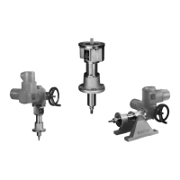
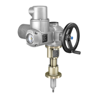
4.2. Actuators for linear thrust units
Assembly is performed in compliance with actuator operation instructions.This
section provides information and indications regarding suitable actuators, flanges,
and screws.
State of delivery
When AUMA actuators and linear thrust units up to size LE 50.1 and a stroke of max.
200 mm are supplied together, assembly is performed in the factory. For larger
strokes and when exceeding size LE 70.1, assembly must be performed by the
customer.The suitable output drive sleeve and the screws for assembly are generally
part of the scope of delivery.
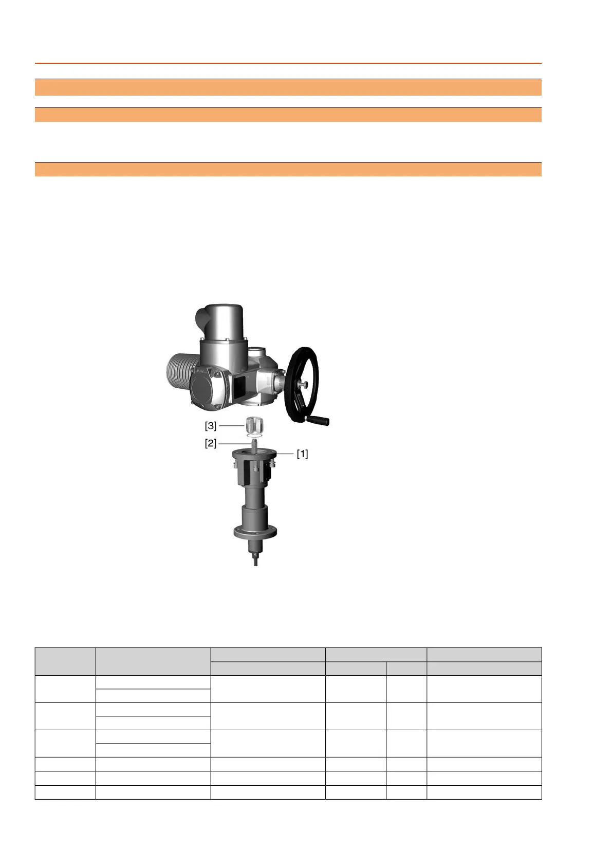
Figure4: Example AUMA multi-turn actuator with LE 25.1
[1] Actuator mounting flange
[2] Stem
[3] Output drive sleeve with circlip
Table 2: Suitable AUMA actuators, flanges, and screws
Tightening torque T
A
[Nm]ScrewsActuator mounting flangeSuitable AUMA actuatorType
Strength class A2-70QuantitySizeEN ISO 5210
364M10 x 30F10, F10-ZB
1)
SA 07.2/SAR 07.2LE 12.1
SVC 05.1/SVCR 05.1
364M10 x 30F10, F10-ZB
1)
SA 07.6/SAR 07.6LE 25.1
SVC 07.1/SVCR 07.1
364M10 x 30F10, F10-ZB
1)
SA 10.2/SAR 10.2LE 50.1
SVC 07.5/SVCR 07.5
1504M16 x 40F14, F14-ZB
1)
SA 14.2/SAR 14.2LE 70.1
1504M16 x 40F14, F14-ZB
1)
SA 14.6/SAR 14.6LE 100.1
2944M20 x 50F16, F16-ZB
1)
, F25
2)
SA 16.2/SAR 16.2LE 200.1
10
LE 12.1 – LE 200.1
Assembly
 Loading...