Mounting flange with 2 holes for pivots1)
Extension flange F16/25 max. input torque 1,000 Nm2)
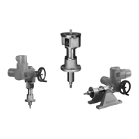
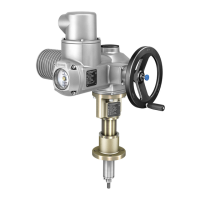
4.3. Linear thrust unit: mount to valve
Mounting position
Mounting is most easily done with the valve shaft pointing vertically upward. But
mounting is also possible in any other position.
The linear thrust unit leaves the factory with retracted thrust rod (stem).
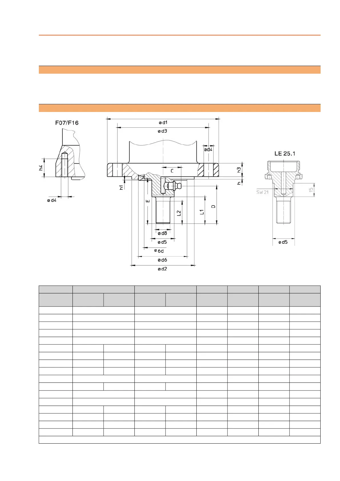
4.3.1. Attachment dimensions for mounting to valve
Table 3: Attachment dimensions to valve
LE 200.1LE 100.1LE 70.1LE 50.1LE 25.1LE 12.1Dimensions
F16
(G3)
F14
(G1/2)
F14
(G1/2)
F10
(–)
F10
(G0)
F07
(G0)
F10
(G0)
F07
(G0)
EN ISO 5210
(DIN 3210)
292626242118C
766363434237D
907575555045
E ±0.2
–––353025L1
655555302520L2
210175175125
1257512575∅ d1
130 f8100 f8100 f870 g770 f8(55 g7 = d6)70 f8(55 g7 = d6)
∅ d2
1651401401021027010270
∅ d3
M2018181111M811M8
∅ d4 (4x)
423636322520
∅ d5
120–––55
1)
–55
1)
–
∅ d6 g7
M42 x 3M36 x 3M36 x 3M20 x 1.5M16 x 1.5M12 x 1.25
∅ d8
1007070554242
∅ d9 –0.1
4443.433.433.4h
0.5–––0.5–0.5–h1
–18181515–15–h3
32––––20–20h4
Grease nipple A-D8 according to DIN 71412
11
LE 12.1 – LE 200.1
Assembly
 Loading...