Spigot for F071)
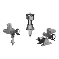
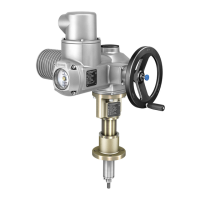
4.3.2. Linear thrust unit: mount to valve
1. Check whether attachment of linear thrust unit suit the valve.
2. Push thrust rod of linear thrust unit to desired position (e.g. OPEN) using the
handwheel.
➥
Assemble valve and actuator in the same end position.
➥
For globe valves, the conventional assembly position is end position CLOSED
(thrust rod is retracted).
3. Clean mounting surfaces (mounting flanges at linear thrust unit and valve).
Thoroughly degrease uncoated mounting surfaces.
4. Place linear thrust unit onto valve as to ensure that bores or thread align with
the mounting flanges.
Information: Ensure that the spigot fits uniformly in the recess and that the
mounting faces are in complete contact.
5. Fasten linear thrust unit with screws and lock washers according to table.
Information: We recommend applying liquid thread sealing material to the
screws to avoid contact corrosion.
6. Fasten screws crosswise to a torque according to table.
Table 4: Tightening torques for screws
Tightening torque T
A
[Nm]Screws
Strength classThreads
A2-80/A4-80A2-70/A4-708.8
241825M8
483651M10
826187M12
200150214M16
392294431M20
7.
Connect coupling stud (∅ d8) of linear thrust unit with valve stem.
Information: The type of connection depends on the valve and is determined
by the valve manufacturer.
8. In case of risk of jamming due to moving parts: Provide protective equipment.
12
LE 12.1 – LE 200.1
Assembly
 Loading...