AUMA Matic Positioner
Calibration Instruction
AUMA Actuators, Inc. USA
Electrical Connections
CAUTION: Observe safety regulations.
• Verify that the motor and control voltages correspond with equipment supplied. Refer to the nameplate on
motor and/or AUMA MATIC Compact.
• Attach conduit or cables following approved practices.
CAUTION: Appropriate conduit and sealing methods must be followed to ensure the NEMA rating for the
enclosure furnished
• Connect field wiring according to wiring diagram supplied. If drawing is not available, contact the nearest
AUMA office with the Sales Order or Serial Number located on the actuator nameplate. A replacement
drawing will be provided.
NOTE: ACTUATOR LIMIT SWITCHES MUST BE SET USING APPROPRIATE SETTING INSTRUCTIONS
PRIOR TO PROCEEDING.
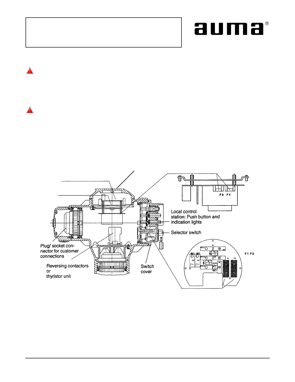
Compartment
Cover
Positioner Board
Logic Board
Power Supply
Monitor Control
Board
Figure 1
AUMA MATIC Controller
All information in this document is subject to change without notice.
ISSUE 02/02 Page 2 of 11 SE-SI-35-0007
 Loading...