AUMA Matic Positioner
Calibration Instruction
AUMA Actuators, Inc. USA
All information in this document is subject to change without notice.
Positioner adjustment for Split Range (See also example below)
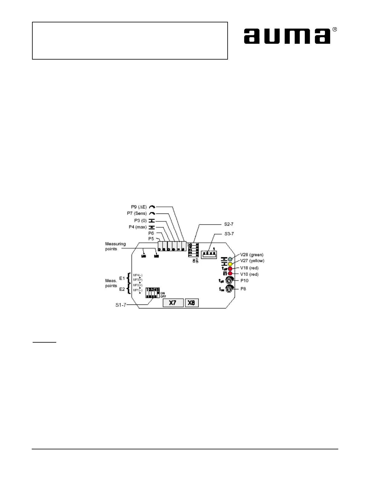
• Supply the specified minimum input signal (nominal value E1) for the positioner and check by measuring with
Voltmeter at the measuring points MP3 and MP4 (Figure 5).
• Connect voltmeter to measuring points M3 and MP1.
Calculate setting value:
Initial value = E 1
min
[in Ampere] x 250 Ohm
Set initial value with potentiometer P5.
• Supply specified maximum command signal (nominal value E1) and check by measuring at the measuring
points MP3 and MP4.
• Connect voltmeter between measuring point M9 and measuring point MP1. Set 5 V with potentiometer P6.
• Supply input signal E1 from minimum to maximum value and check the set range 0 - 5 V at measuring point
M9. If necessary, readjust with P5 or P6.
• Apply the same procedure to the second actuator’s positioner and set according to the specified nominal
value E1.
• After setting for Split Range operation, perform further readjustment as described in Calibration section, Page 6.
Figure 4
Positioner board A7, Split Range version
Example – Two actuators are to be operated in Split Range version. Actuator 1 must be in position CLOSED with
a nominal value signal E1 of 0 mA, and in position OPEN with a signal of 10 mA.
Actuator 2 must be in position CLOSED with a nominal value signal of 10 mA, and in position OPEN with a signal
of 20 mA. .
• Positioner actuator 1:
Supply E1 = 0 mA, set with P5 = 0 V at M3, supply E1 = 10 mA, set with P6 = 5V at M9.
• Positioner actuator 2:
Supply E1 = 10 mA, set with P5 = 2,5 V at M3, supply E1 = 20 mA, set with P6 = 5V at M9.
• Perform adjustments and settings for E2, as previously described. Afterwards the nominal value E1 can be
transmitted through both actuators (can be connected in series). When operating within range E1 = 0 - 10
mA the actuator 1 moves, actuator 2 remains in end position CLOSED. When operating within range E1 = 10
- 20 mA, the actuator 2 moves, actuator 1 remains in end position OPEN.
ISSUE 02/02 Page 9 of 11 SE-SI-35-0007
 Loading...