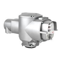
AUMA Matic Positioner
Calibration Instruction
AUMA Actuators, Inc. USA
Test Run
• Switch selector switch to local position. If local control is not supplied, refer to electrical drawing for reference
to local operation.
• Turn control switch or operate push-button in either open or close direction.
If actuator fails to operate, verify the following possible conditions.
NOTE: 3Ø AUMA MATIC compacts incorporate a phase discriminator. If AUMA MATIC fails to respond to local
and remote operation, reverse U1 and W1 at field terminals.
NOTE: Actuators shipped after March 2002 incorporate automatic phase correction.
• No line power.
— Check for loose connection.
— Check for correct voltage at terminals U1, V1 and W1.
— Check for correct capacitor connection (1Ø only), if required.
• Field jumpers are not correct.
— Verify the field wiring matches electrical drawing supplied by AUMA.
• Fuses are open.
CAUTION: Before checking/replacing fuses, ensure all power is disconnected.
— Remove selector switch/push-button cover (Figure 1). Primary fuse(s) are located in black fuse holders.
— Secondary fuses are located on power supply board which can be accessed by removing the monitor
control circuit board where the primary fuse(s) are located.
NOTE: Replace fuse(s) with same type and size. For fuse sizes, refer to appropriate service instruction or
consult factory.
Calibration Description and Preparation
Technical Data
Input Signals (E1): 4-20 ma / 0-20 ma; 0-5v DC (for others, consult factory)
Feedback (E2): 0-5v via precision potentiometer, typical
Sensitivity: 0.5 to 2.5 percent (0.25 min ≤ 19 rpm)
Time Delay: 0.5 to 15 seconds
LED Indication: OPEN/CLOSE/PAUSE; loss of command signal.
Input Resistance: 249 Ω
All information in this document is subject to change without notice.
ISSUE 02/02 Page 4 of 11 SE-SI-35-0007

 Loading...