AUMA Matic Positioner
Calibration Instruction
AUMA Actuators, Inc. USA
All information in this document is subject to change without notice.
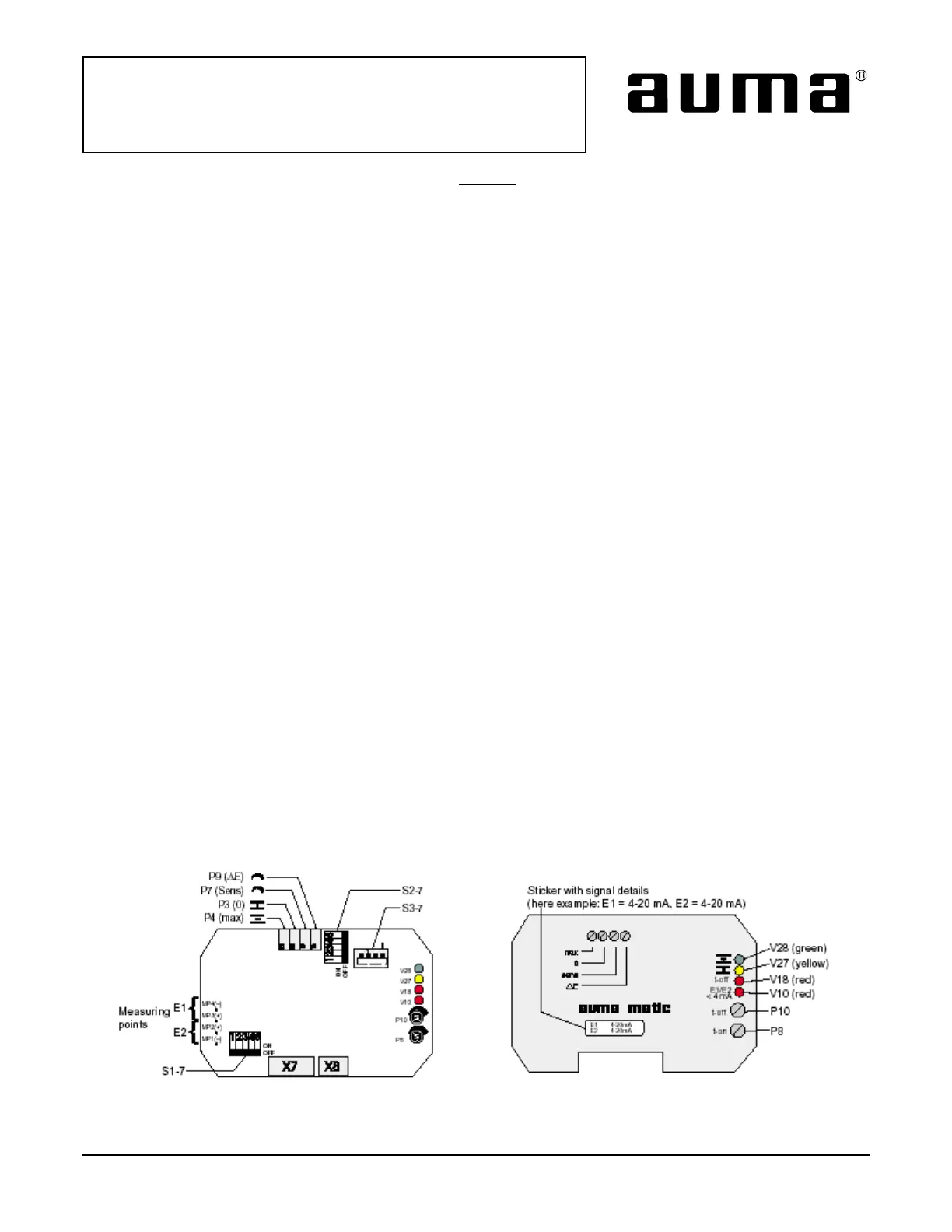
The AUMA Matic positioner incorporates the following features for field calibration and commissioning (Figure 3).
ZERO (0/P3) This control adjustment calibrates the positioner to correspond to the lowest command
signal.
SPAN (max/P4) This control adjustment calibrates the positioner to the full 100 percent range of the
command signal.
TIME DELAY This control adjustment is designed to eliminate the positioner
(t-off/P10) from reacting to transient signals. Adjustable delay from 0.5 seconds to 15 seconds.
COARSE SENSITIVITY This control adjustment determines the amount of error signal that occurs before
(∆E/P9) the motor is energized in the direction determined by the input signal, 0.5 to 2.5
percent.
FINE SENSITIVITY This control adjustment determines the amount of error signal that occurs before the
(Sens/P7) motor is energized in the direction determined by the input signal. This is only used for
actuator speeds of 19 RPM and below, where less than 0.5 percent accuracy is
required (0.25 percent minimum).
DIP SWITCH S1-7 Allows command signal (E1) and feedback signal (E2) to be selected.
DIP SWITCH S2-7 Allows controller to position the actuator on loss of command or feedback signal. In
addition, variable pulse width modulation can be selected.
DIP SWITCH S3-7 Selects standard or inverse operation.
TIME-ON (t-on/P8) Allows calibration of initial “ON” times in the pulsing mode.
V10 LED - loss of E1, or wrong polarity
V18 LED - pause mode (pulse width modulation).
V27 LED - closing circuit energized
V28 LED - opening circuit energized
MP1,MP2,MP3,MP4 Test points - MP1 = common; MP2 = feedback (E2); MP3 = input (E1);
MP4 = common (E1)
E1 Input signal
E2 Feedback signal
Positioner Board Positioner Cover Plate
Figure 3
ISSUE 02/02 Page 5 of 11 SE-SI-35-0007
 Loading...